Installation Guide 13
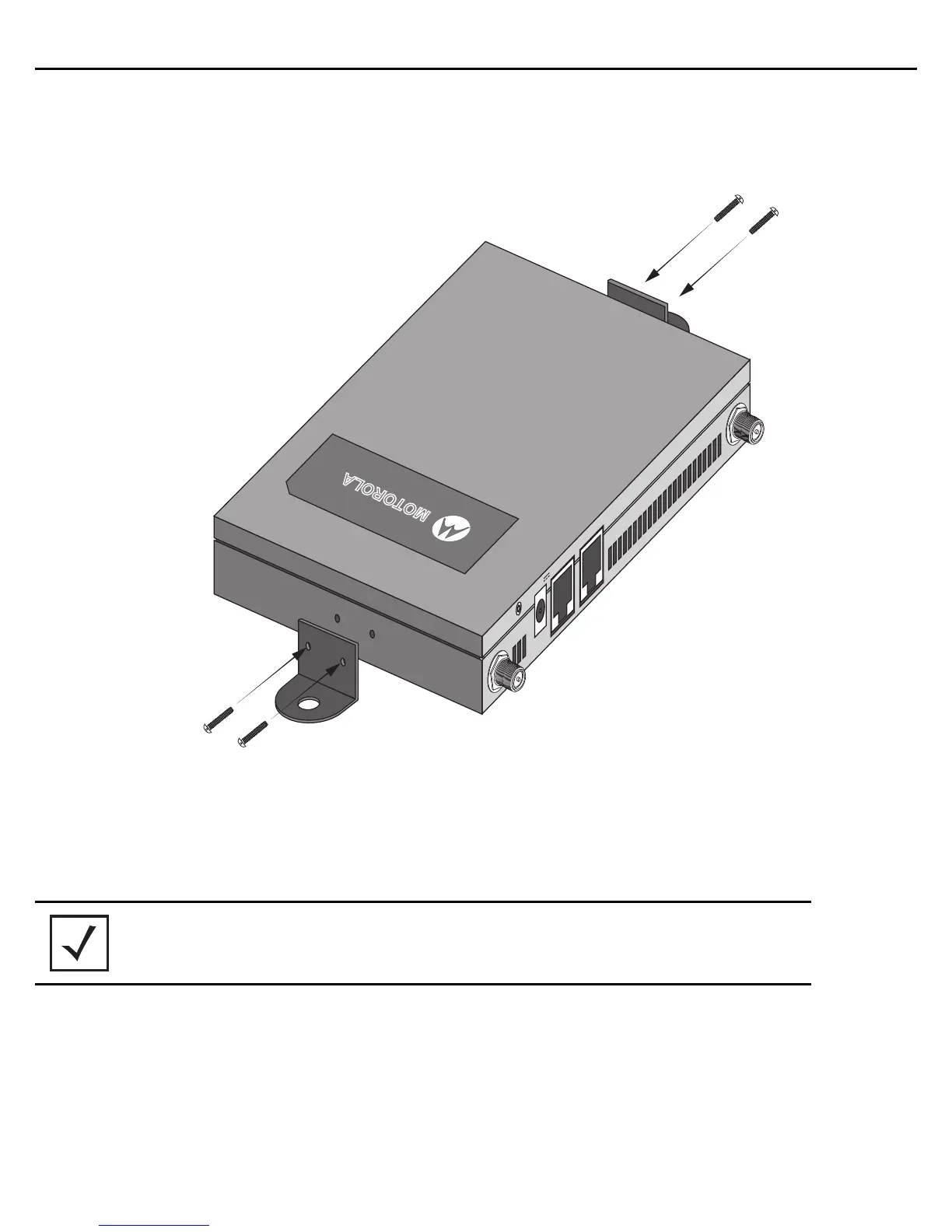
1. Attach the two provided mounting ears (using four ear mounting screws) to the two narrow ens of the
AP6522. Align the ears using the built in ear alignment pin on the access point housing. Torque the screws
to 6 lb-in.
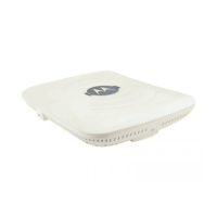
2. Place the access point against the wall, ensuring the access point’s Motorola Solutions “bat wings” logo
is in the correct orientation.
3. Mark the screw hole locations on a vertical axis using the ear’s mounting holes.
4. At each point, drill a hole in the wall and insert the anchor.
5. Place the access point on the anchor. Insert screws through the access point’s mounting ears and into the
anchor.
6. If required, install and attach a Kensington security cable (customer supplied) to the unit’s lock port.
7. Attach an Ethernet cable from the access point to a controller with an 802.3af-compatible power source
or use the PWRS-14000-148R power supply to supply power to the AP6522 (once fully cabled).
8. Attach appropriate antennas to the connectors.
NOTE When pre-drilling a hole the recommended hole size is 2.8mm (0.11in.).
RADIO2-1 RADIO1-0DC 12V GE1/PoE Console
MOTOROLA
 Loading...