Controller Theory of Operation 2-9
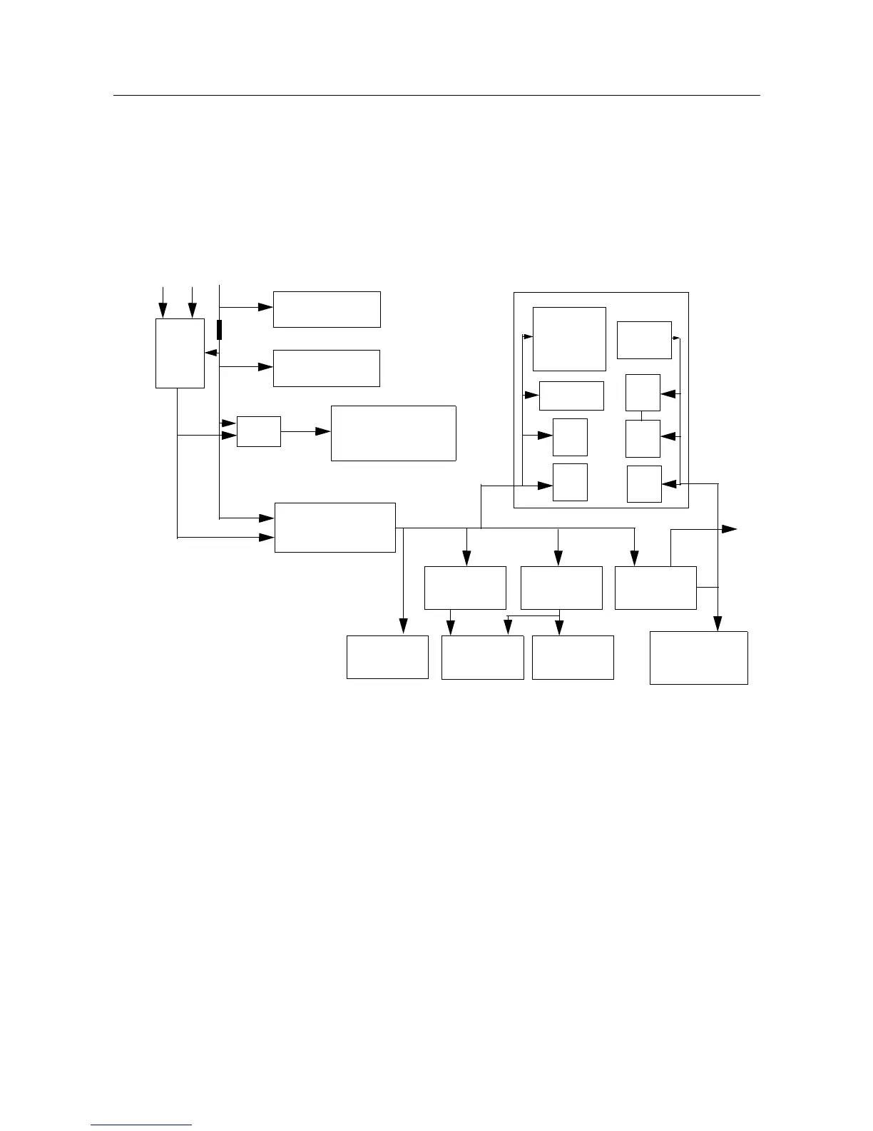
The DC voltage applied to connector P2 supplies power directly to the following circuitry:
• Electronic on/off control
• RF power amplifier
• 12 volts P-cH FET -U514
• 9.3 volt regulator
• Audio PA
Figure 2-6 DC Power Distribution Block Diagram
Regulator U501 is used to generate the 9.3 volts required by some audio circuits, the RF circuitry
and power control circuitry. Input and output capacitors are used to reduce high frequency noise.
Resistors R5001 / R5081 set the output voltage of the regulator. This regulator output is
electronically enabled by a 0 volt signal on pin 2. Q502, Q505 and R5038 are used to disable the
regulator when the radio is turned off.
Voltage regulator U510 provides 3.3 volts for the digital circuitry. Operating voltage is from the
regulated 9.3V supply. Input and output capacitors are used to reduce high frequency noise and
provide proper operation during battery transients. U510 provides a reset output that goes to 0 volts
if the regulator output goes below 3.1 volts. This is used to reset the controller to prevent improper
operation.
Voltage regulator U508 provides 3.3V for the RF circuits and ASFIC_CMP. Input and output
capacitors are used to reduce the high frequency noise and provide proper operation during battery
transients.
U501
9.3V Regulator
FET
P-CH
On/Off
Control
500mA
SW_Filt_B+
Acces Conn
Audio PA_Soutdown
Power Loop Op_Amp
Auto
On/Off
Switch
Control
Ignition
B+
RF_PA
Audio_PA
Antenna Switch
Power Control
Filt_B+
Ferrite Bit
Control Head
Mic Connector
Mic Bias
9V, 5mA
Keypad
7_Seg
Bed
to
7-Seg
Shift
Reg
3.2V
72mA
9.3V
65mA
Status LEDs
7_Seg
DOT
Back
light
On/Off
Control
11-16.6V
0.9A
0.85A
U503
5V RF Regulator
U508
3.3V RF Reg
U510
3.3V D Reg
Reset
Rx_Amp
PA_Pre-driver
PA Driver
500mA
LVFRAC_N
IF_Amp
ASFIC_CMP
IFIC
RX Cct
micro P
RAM
Flash
EEPROM
90mA
25mA50mA45mA
9.3V
45mA
9.3V
75mA
9.3V
162mA
 Loading...