Chapter 4
VHF1 PCB/ SCHEMATICS/ PARTS LISTS
1.0 Allocation of Schematics and Circuit Boards
1.1 VHF1 and Controller Circuits
The VHF circuits are contained on the printed circuit board (PCB) which also contains the Controller
circuits. This Chapter shows the schematics for both the VHF circuits and the Controller circuits. The
PCB component layouts and the Parts Lists in this Chapter show both the Controller and VHF circuit
components. The VHF and Controller schematics and the related PCB and parts list are shown in
the tables below.
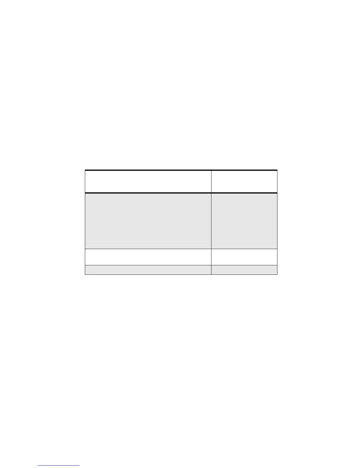
Table 4-1 VHF1 1-25W Diagrams and Parts Lists
PCB :
8486672Z01 Main Board Top Side
8486672Z01 Main Board Bottom Side
Page 4-4
Page 4-5
SCHEMATICS
Main Circuit
Transmitter
Synthesiser and VCO
Receiver Front and Back End
DC and Audio Ccts
Microprocessor and Controller Ccts
Power Control Cct
Page 4-6/Page 4-7
Page 4-8/Page 4-9
Page 4-10/Page 4-11
Page 4-12/Page 4-13
Page 4-14/Page 4-15
Page 4-16/Page 4-17
Page 4-18
Parts List
8486672Z01 Page 4-19
Controller version is T1
 Loading...