Do you have a question about the Motorola Commercial CM Series and is the answer not in the manual?
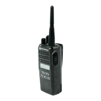
| Scanning | Yes |
|---|---|
| Frequency Range | VHF: 136-174 MHz |
| Channel Capacity | 16 |
| Operating Temperature | -30°C to +60°C |
| Waterproof | IP54 |
| Programmable Buttons | 2 programmable buttons |
| VOX | Yes |
| Battery Type | Li-Ion or NiMH |
Lists model numbers and their descriptions, including channel capacity.
Details general and specific technical parameters like frequency, stability, power, and operating conditions.
Provides an overview of the chapter's content covering UHF circuits and controller circuits.
Explains the operational theory of the UHF receiver's front-end and back-end stages.
Explains the three-stage transmitter power amplifier design and components.
Covers the synthesizer system including oscillator, LVFRAC-N, and VCO components.
Explains the radio's controller architecture, operation, and connected components.
Describes the SRAM's role in temporary calculations and data storage during operation.
Covers the audio and signaling circuits located on the control board.
Explains the paths for transmit audio signals from microphone to RF section.
Covers the circuits responsible for transmitting signaling data.
Explains the paths for received audio signals from IF IC to speakers.
Covers circuits for receiving and decoding signaling data.
Provides a flowchart for diagnosing receiver RF issues.
Continues the receiver troubleshooting flowchart.
Offers a flowchart for diagnosing 25W transmitter problems.
Continues the transmitter troubleshooting flowchart.
Completes the transmitter troubleshooting flowchart.
Provides a flowchart for troubleshooting the synthesizer circuit.
Offers a flowchart for diagnosing issues with the Voltage Controlled Oscillator.
Begins a flowchart for troubleshooting DC power supply voltages.
Continues the DC supply troubleshooting flowchart.
Outlines the document's structure regarding schematics and parts lists.
Identifies schematics and parts for UHF and controller circuits.