3-4 TROUBLESHOOTING CHARTS
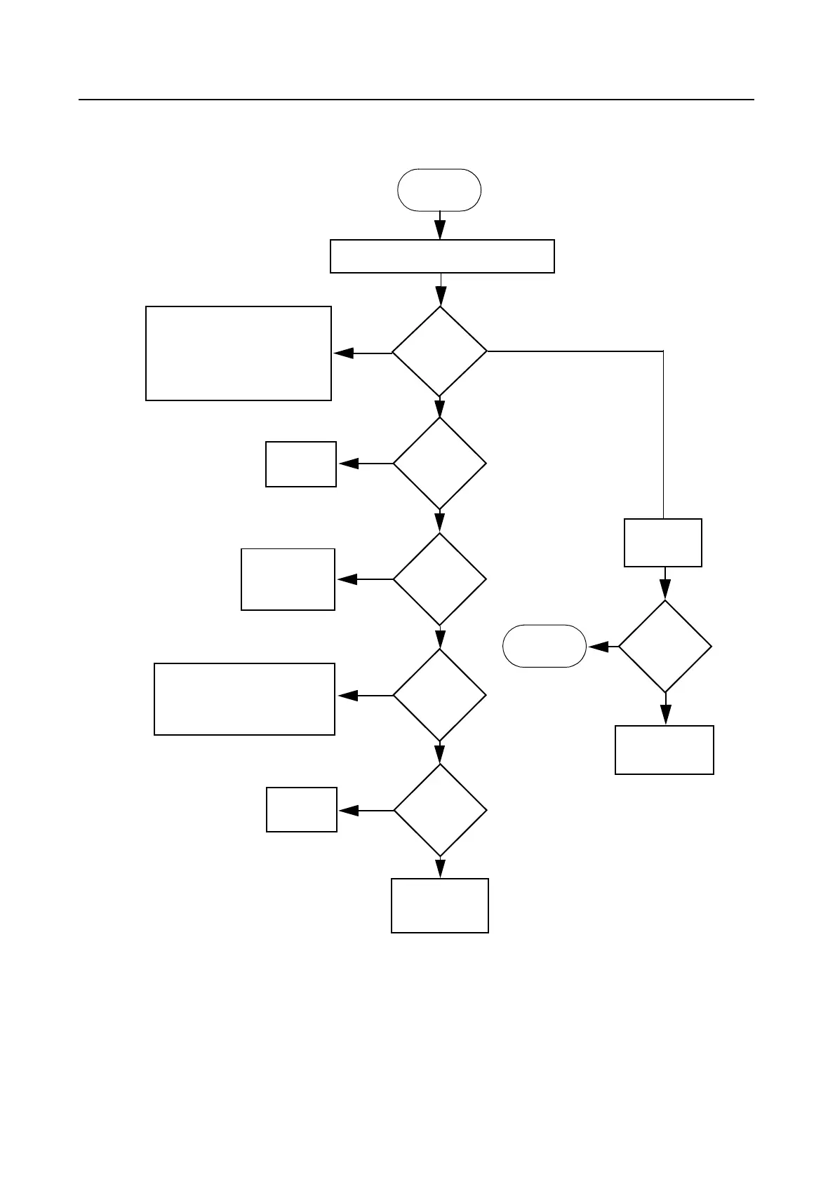
2.0 Troubleshooting Flow Chart for 25W Transmitter (Sheet 1 of 3)
START
Yes
No
Check components between
Q100 and RF output,
Antenna Switch D104, D103,
VR102 and Q106
Before replacing Q100.
No or too low power when keyed
Current
increase when
keyed?
Check power settings, tuning
& components between U103
Pin 3 and ASFIC Pin 6 before
replacing ASFIC
Control
Voltage at
TP150
>1.6V?
Check PA
Stages
>1A
Voltage U103
pin 5 =
4.7V?
U103 Pin 3
<2.6Vdc
PA Bias
Voltage@R134
>2Vdc
Check 9.3V
Regulator
U501, R180 &
R181
Yes
Yes
No
No
Yes
Check
U103
Check Forward
Power Sense
Circuit
No
Short U100
Pin 3 to
ground
Voltage at
TP150 rises?
Check PA
Stages
Check Forward
Power Sense
Circuit
Yes
No
>800mA & <1A
<800mA

 Loading...