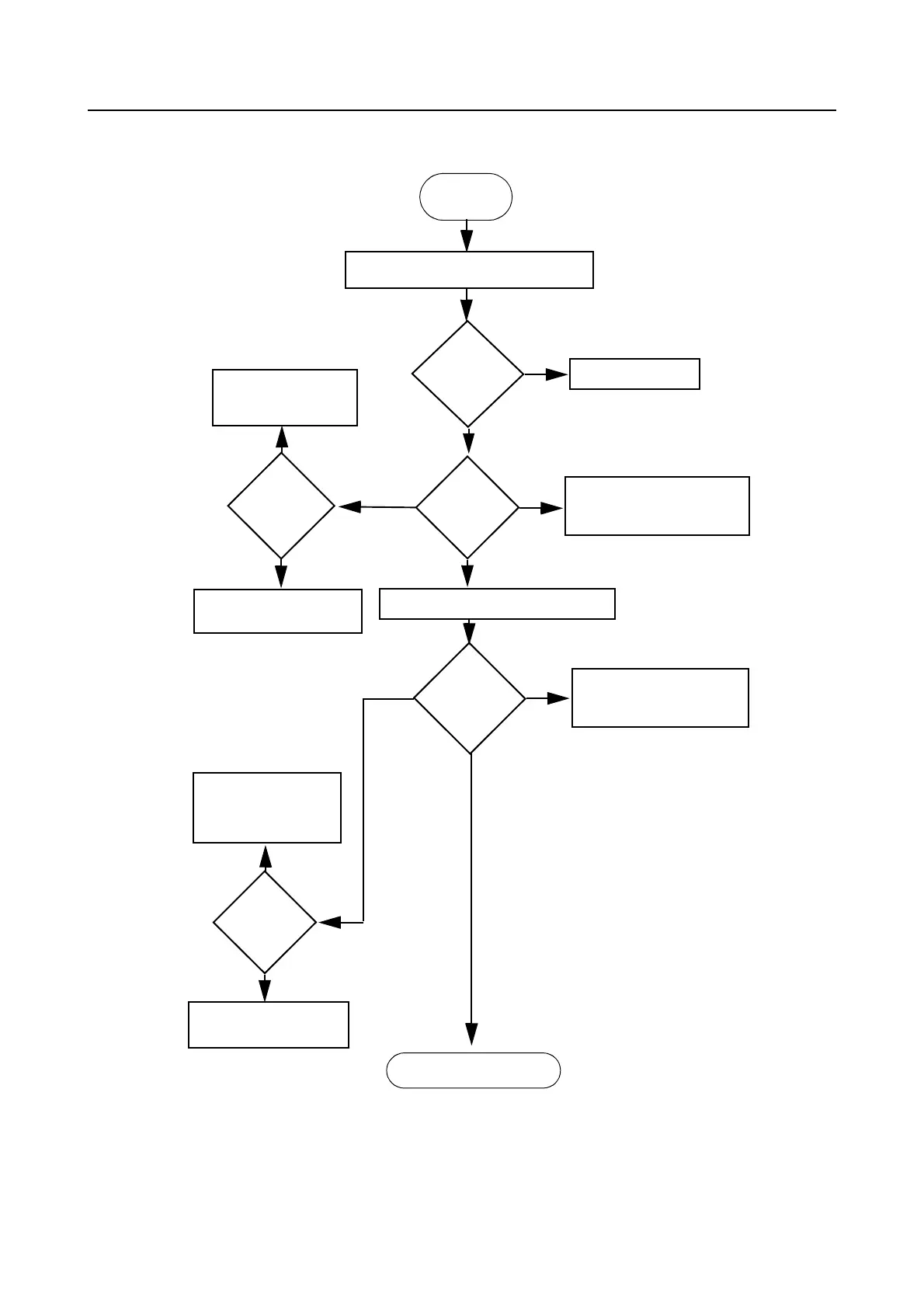
Troubleshooting Flow Chart for 25W Transmitter (Sheet 1 of 3) 3-5
2.1 Troubleshooting Flow Chart for 25W Transmitter (Sheet 2 of 3)
Yes
>3V
Check Q102, R139,
R155, R166, R126-
R128, R169, R138,
R175, R147
Check PA
Stages
No or too low power when keyed
DC
Voltage
at Q101 & Q102
base=0?
DC
Voltage
at U103
Pin 8
Check U403
Check resistive network at
Pin 9 and 10 of U103
before replacing U101
Measure DC Voltage at U102 Pin 1
Pin 1
Voltage
Check resistive network at
Pin 2 & 3 of U102 before
replacing Q105
Check Final PA Stages
DC
Voltage
U102 Pin 3 =
8.7V
Check U102 before re-
placing Q105
DC
Voltage at
U103 Pin
10=8.9V
Check Q101, Q102,
R153, R136, R165,
R122, R168 & R137
Check U103 before re-
placing U101
No
No
Yes
>4.5V
3.5 to 4.5V
2-3V
Yes
No
<3.5V
<2V

 Loading...