Do you have a question about the Motorola 6864115B62-C and is the answer not in the manual?
Standard copyright notice for Motorola computer programs.
Describes the manual's intended audience and currency.
Outlines Motorola's product support during and after the warranty period.
Provides contact information for technical support services to resolve malfunctions.
Explains how to determine radio model characteristics from the label.
Outlines the topics covered in the maintenance chapter.
Recommends periodic visual inspection and cleaning for radios.
Provides procedures for cleaning external and internal radio surfaces using recommended agents.
Discusses precautions for handling CMOS and LDMOS devices to prevent damage.
Covers rework procedures and the use of lead-free solder wire and components.
Lists service aids recommended for radio work, including part numbers and applications.
Lists test equipment required for servicing radios, including characteristics and applications.
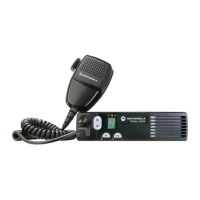
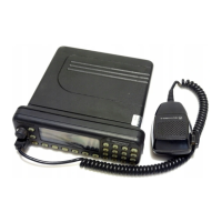
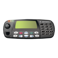
Provides an overview of different GM Series control head models.
Explains the theory of operation for control head circuits.
Provides troubleshooting flowcharts for control heads.
Lists models and accessories for GM140 and GM160.
Lists models and accessories for GM340, GM360, and GM380.
Provides general technical specifications for GM Series radios.
Explains the theory of operation for the VHF receiver section.
Details the operation of the 25W power amplifier stages.
Explains the theory of operation for the VHF frequency synthesizer subsystem.
Provides a flowchart for troubleshooting receiver issues.
Troubleshooting flowchart for 25W transmitter issues.
Troubleshooting flowchart for synthesizer issues.
Schematic diagrams for VHF 1-25W PCB 8486172B04.
Schematic diagrams for VHF 1-25W PCB 8486172B06.
Schematic diagrams for VHF 1-25W PCB 8486172B07.
Schematic diagrams for VHF 1-25W PCB 8486172B08.
Schematic diagrams for VHF 25-45W PCB 8486140B12.
Schematic diagrams for VHF 1-25W PCB 8471235L02.
Lists models and accessories for GM140 and GM160.
Lists models and accessories for GM340, GM360, and GM380.
Provides general technical specifications for GM Series radios.
Explains the theory of operation for the UHF receiver section.
Details the operation of the 25W power amplifier stages.
Explains the theory of operation for the UHF frequency synthesizer subsystem.
Provides a flowchart for troubleshooting receiver issues.
Troubleshooting flowchart for 25W transmitter issues.
Troubleshooting flowchart for UHF 40W transmitter issues.
Troubleshooting flowchart for synthesizer issues.
Shows schematics and parts lists for UHF circuits.
Schematic diagrams for UHF 1-25W PCB 8485670Z02.
Schematic diagrams for UHF 25-40W PCB 8480643Z06.
Schematic diagrams for UHF 1-25W PCB 8485670Z03.
Schematic diagrams for UHF 1-25W PCB 8486127Z01.
Schematic diagrams for UHF 1-25W PCB 8471224L01.
Schematic diagrams for UHF 1-25W PCB 8471224L03.
Lists models and accessories for GM360 radios.
Provides general technical specifications for GM360 radios.
Introduces the theory of operation for Low Band circuits.
Explains the theory of operation for the Low Band receiver section.
Details the operation of the 25-60W Low Band power amplifier stages.
Explains the theory of operation for the Low Band frequency synthesizer subsystem.
Troubleshooting flowchart for low band transmitters.
Troubleshooting flowchart for low band receiver issues.
Troubleshooting flowchart for synthesizer issues.
Troubleshooting flowchart for Low Band VCO issues.
Allocates schematics and parts lists for Low Band circuits.
Schematic diagrams for LB1 25-60W PCB 8486206B06.
Schematic diagrams for LB2 25-60W PCB 8486207B05.
Schematic diagrams for LB3 25-60W PCB 8485908Z03.
Schematic diagrams for LB1 25-60W PCB 8486206B08.
Schematic diagrams for LB2 25-60W PCB 8486207B07.
Schematic diagrams for LB3 25-60W PCB 8485908Z04.