EasyManua.ls Logo

Motorola 6864115B62-C

Motorola 6864115B62-C
452 pages
To Next Page IconTo Next Page
To Previous Page IconTo Previous Page
Loading...
Chapter 3
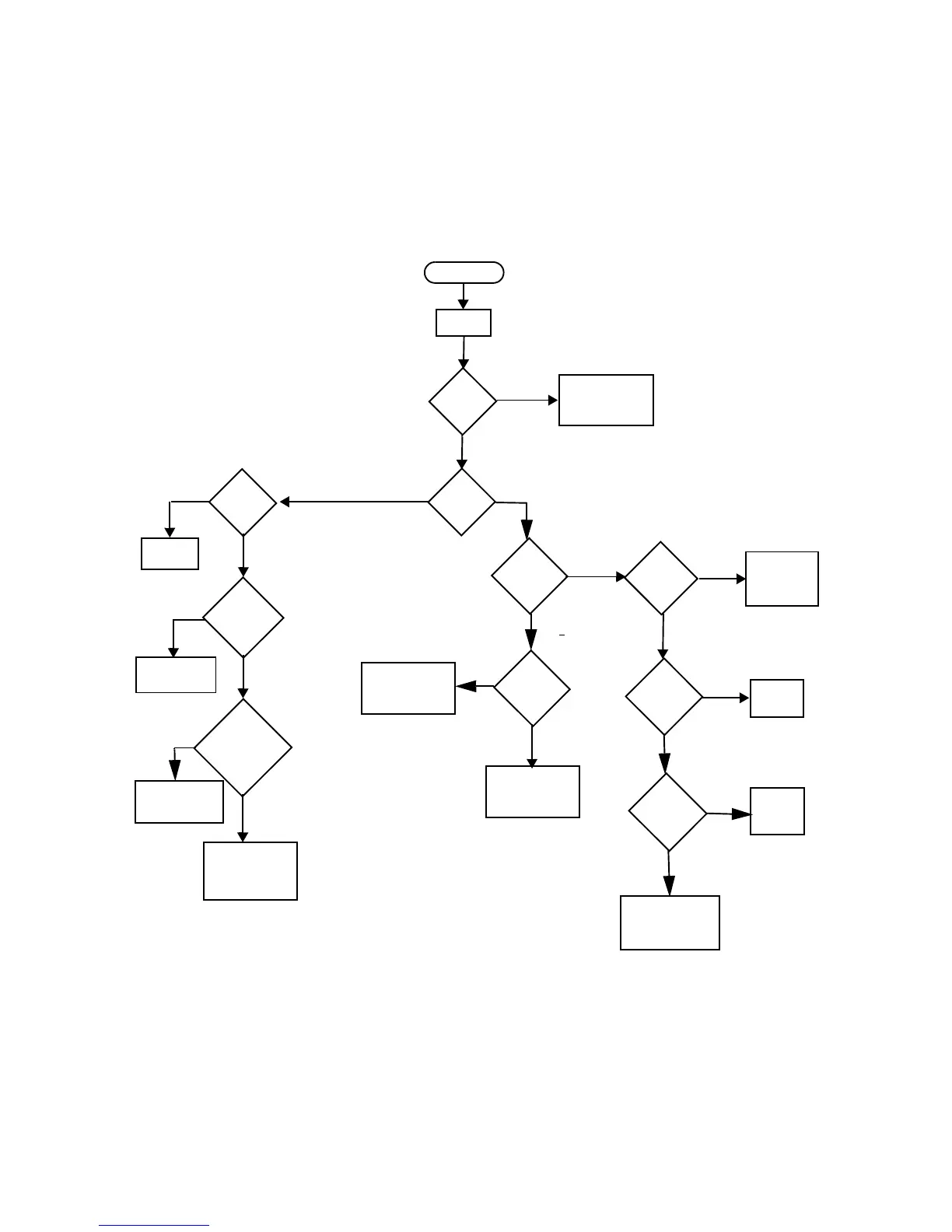
LOW BAND TROUBLESHOOTING CHARTS
1.0 Troubleshooting Flow Chart for Transmitter
No
DC
@ Gate of
Q1401
Voltage
?
No
Yes
START
No or Low
TX
DC
@Drains of
Q1402 &
Q1403
Voltage
?
@ Cathode of
D1401 &
D1402
DC
Voltage
?
Drains of Q1402 &
AC
Q1403 both sine or
both distorted
Voltages @
?
Check 9T1 and
Diode Bias Circuit
Verify RF Continuity
to gates of
Q1402 & Q1403
Check circuitry
between Q1402 &
Q1403 and
Antenna Port
Check
MOSBIAS_1
Supply and
Feed Network
No
<<18V pp
Yes
No
Yes
<
1A
No
Check
Q1401
Device
Yes
CURRENT
RF @
Junction
R1413 &
DC
@ TP1402 &
TP1403
Yes
Check
MOSBIAS_2
MOSBIAS_3
and Feed Networks
Check DC/AC
Gate Circuits of
Q1402 & Q1403
Check Supply Feed
and/or PowerControl
Circuits.
No
>18V pp
Check
U1401
Device
AC
@ Gate of
Q1401
Voltage
?
Yes
DC
@ U1401
Voltage
?
Yes
No
Power Out
>
1A
Look for
short on
Supply Line
R1414
Voltage
?
TX
Safety
Switch
Check Pressure Pad
and/or
Switch Circuitry

Table of Contents

Related product manuals