Chapter 1
MODEL CHART AND TECHNICAL SPECIFICATIONS
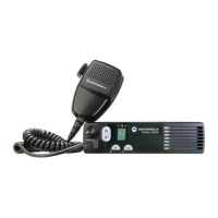
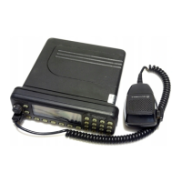
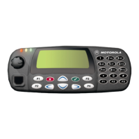
1.0 GM360 Model Chart
2.0 Technical Specifications
Data is specified for +25°C unless otherwise stated.
GM Series Low Band 29-50 MHz
Model Description
MDM25BKF9AN5_E GM360 LB1, 29.0-36.0 MHz, 25-60W, 255 Ch
MDM25CKF9AN5_E GM360 LB2, 36.0-42.0 MHz, 25-60W, 255 Ch
MDM25DKF9AN5_E GM360 LB3, 42.0-50.0 MHz, 25-60W, 255 Ch
Item Description
XXXGCN6114_ Control Head, GM360
X IMUB6003_S Field Replaceable Unit (Main Board) GM360
X IMUB6004_S Field Replaceable Unit (Main Board) GM360
X IMUB6005_S Field Replaceable Unit (Main Board) GM360
XXXENBN4056_ Packaging, Waris Mobile
X X X HKN9402_ 12V Power Cable
XXXMDRMN4025_ Enhanced Compact Microphone
X X X RLN4774_ 3 Point Mount
XXX6864110B81_ User Guide, GM360
X = Indicates one of each is required
General Specifications
Channel Capacity
GM360
255
Power Supply 13.2Vdc (10.8 - 15.6Vdc)
Dimensions: H x W x D (mm) Height excluding knobs GM360
59mm x 179mm x 250mm
(add 9mm for Volume Knob)
Weight 2064gr
Sealing: Withstands rain testing per
MIL STD 810 C/D /E and IP54
Shock and Vibration: Protection provided via impact
resistant housing exceeding MIL STD
810-C/D /E and TIA/EIA 603
Dust and Humidity: Protection provided via environment
resistant housing exceeding MIL STD
810 C/D /E and TIA/EIA 603
 Loading...