EasyManuals Logo

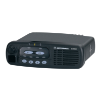
Motorola GM Series Service Information

Motorola GM Series
34 pages
To Next Page IconTo Next Page
To Previous Page IconTo Previous Page
Page #29 background imageLoading...
Page #29 background image
Troubleshooting Flow Chart for 45W Transmitter (Sheet 1 of 2) 3-7
3.1 Troubleshooting Flow Chart for Transmitter (Sheet 2 of 2)
Pin 2
Voltage 0.62
* Voltage at
Pin 1?
NO
YES
Check PA Stages
No or too low Power when keyed
NO
YES
Replace U3401
Pin 3
Voltage 0.51
* Voltage at
Pin 1?
2-4V
Supply
0V
Bias 1 DC
Voltage at
TP3406?
NO
YES
PCIC U3501
Pin 24 2-4V
DC?
Check Bias Tuning be-
fore replacing
PCIC U3501
Check Voltage at Pin 2 & 3 of U3401
Replace U3401
Replace Q3421
NO
0V
1-4V
Bias 2 DC
Voltage at
TP3407?
YES
RF Voltage
at TP3401
>100mV?
YES
RF Voltage
U3401 Pin 6
>3V?
Replace
Q3421
Supply
Replace Q3431
Check FGU (U3301)
NO
Check Components
between TP3401 &
C3417
NO
YES
ASFIC
U0221 Pin 6
1-4V DC?
Check Bias Tuning be-
fore replacing
ASFIC U0221
Check Components
between ASFIC and
Q3431 before re-
placing Q3431
YES
RF Voltage
Q3421 Gate
>1V?
NO
Check Components
between C3417 &
Q3421
YES
RF Voltage
Q3431 Gate
>4V?
NO
Check Components
between Q3421 &
Q3431
YES
RF Voltage
Q3441 Base
>5V?
Check Components
between Q3431 &
Q3441
NO
Check Components
between Q3441 & An-
tenna Connector
Voltage
Voltage

Table of Contents

Other manuals for Motorola GM Series

Questions and Answers:

Question and Answer IconNeed help?

Do you have a question about the Motorola GM Series and is the answer not in the manual?

Motorola GM Series Specifications

General IconGeneral
Channels16
WaterproofNo
Frequency RangeVHF: 136-174 MHz
SignalingDTMF, MDC1200
Dimensions56 x 175 x 218 mm

Related product manuals