2-6 REDUCING NOISE INTERFERENCE
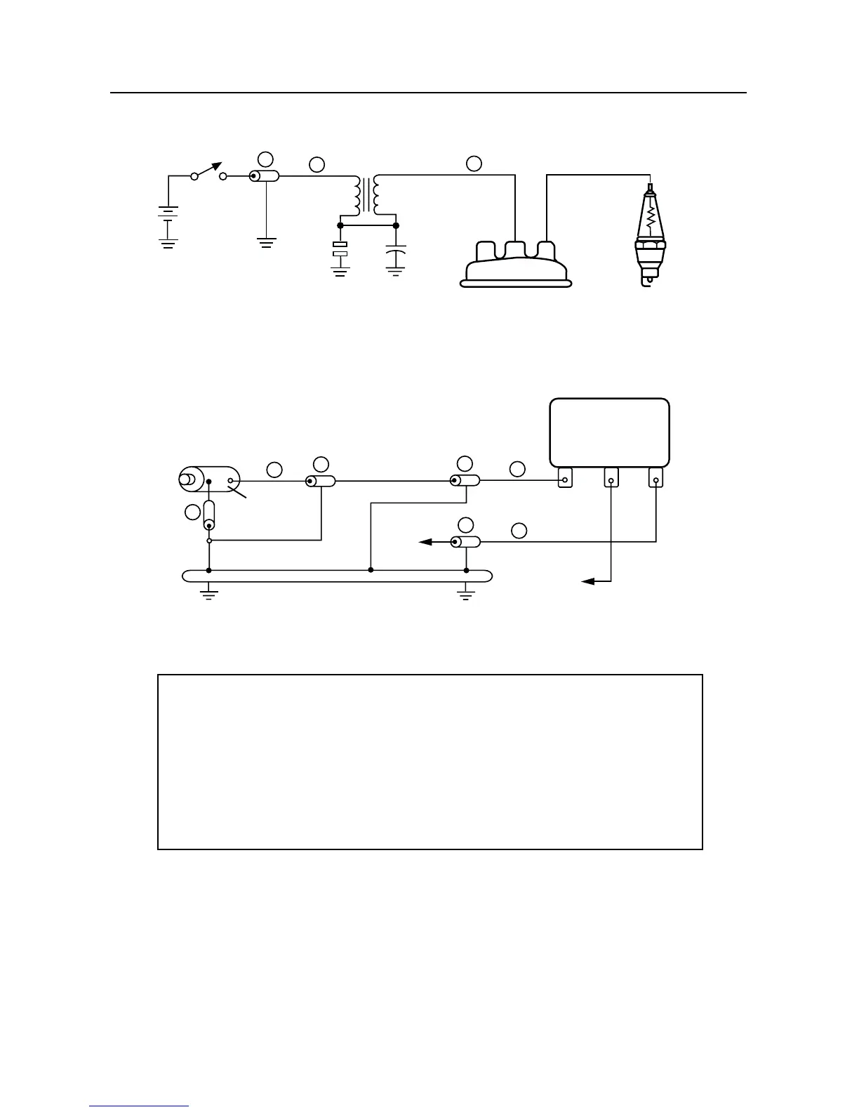
Figure 2-4 TLN6252_ Noise Reduction Kit for Generator-Equipped Vehicles
Generator
Ignition
Switch
Battery
Ignition
Coil
Distributor
Breaker
Points
Resistive Wire
(Note 2)
Resistor
Spark Plugs
(Note 2)
Armature
Field
Common Ground
To
Battery
To
Generator
Field
Voltage Regulator
ARM
FLD
BAT
Notes:
1. Noise reduction can only be achieved if components are grounded properly.
Be sure that all the capacitors and the generator filed suppressor assembly are
grounded properly. This may require bonding straps for proper bypass
capacitor effectiveness.
2. Items not supplied in kit. See auto parts dealer.
FL0830263-O
1
2
3
4
5
6
1
4
1
4
FL0830263-O
Reference Quantity Motorola Description
Number Part Number
1 3 0100839913 Lead & Lug Assembly
2 1 0180700A88 Lead & Lug Assembly
3 1 0882571B02 Capacitor, Coaxial (0.1µF, 100V)
4 3 0882571B01 Capacitor, Coaxial (0.5µF, 100V)
5 1 0180700A89 Generator Field Suppressor Assembly
6 1 3000502396 Ignition Coil Suppressor Cable
- 1 0180700A91 Hood Wipers (2) and Mounting
Hardware Kit (not illustrated).

 Loading...


