General Repair Procedures and Techniques 2-3
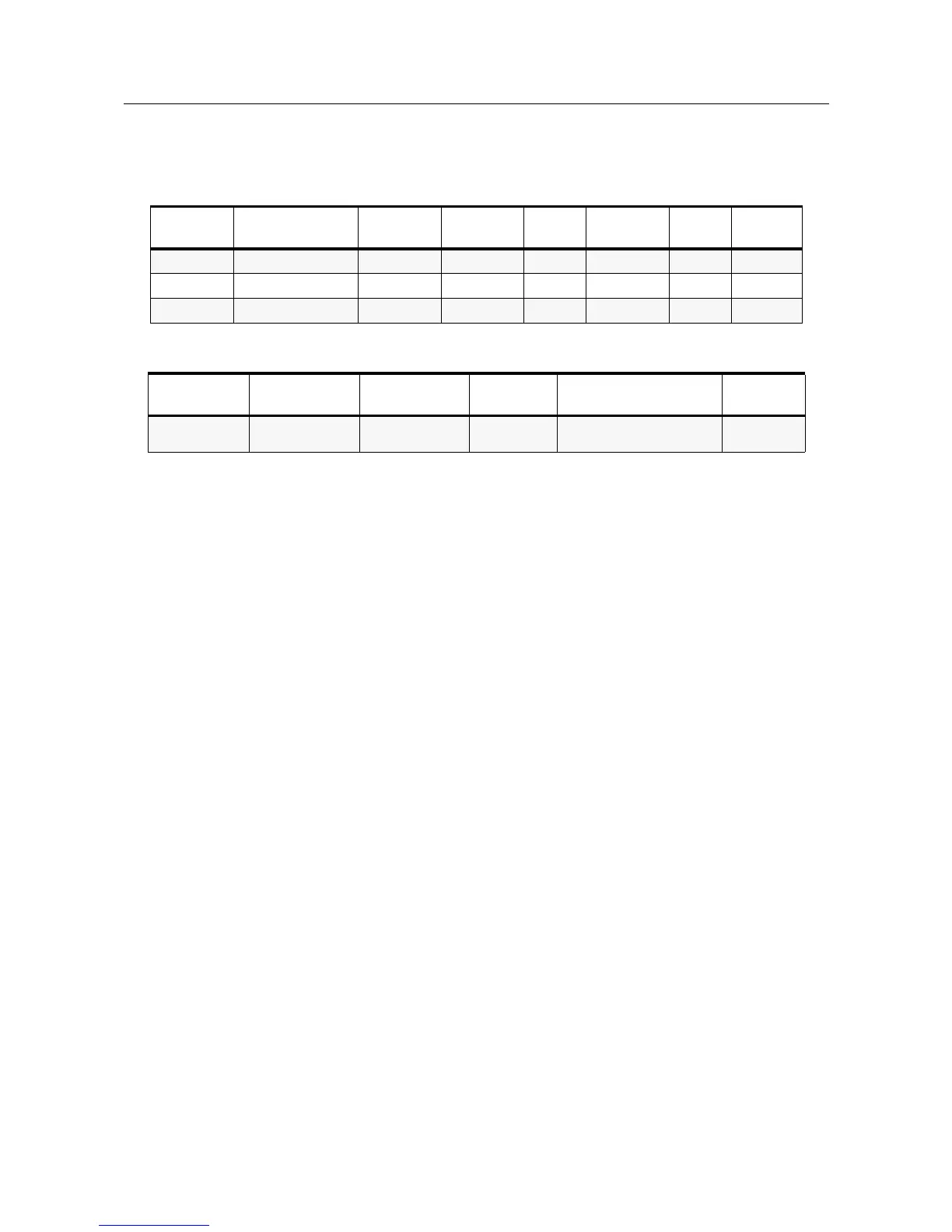
Any rework or repair on Environmentally Preferred Products must be done using the appropriate
lead-free solder wire and lead-free solder paste as stated in the following table:
Parts Replacement and Substitution
When damaged parts are replaced, identical parts should be used. If the identical replacement
component is not locally available, check the parts list for the proper Motorola part number and
order the component from the nearest Motorola Communications parts center listed in the “Piece
Parts” section of this manual.
Rigid Circuit Boards
The family of radios uses bonded, multi-layer, printed circuit boards. Since the inner layers are
not accessible, some special considerations are required when soldering and unsoldering
components. The through-plated holes may interconnect multiple layers of the printed circuit.
Therefore, care should be exercised to avoid pulling the plated circuit out of the hole.
When soldering near the 18-pin and 40-pin connectors:
• avoid accidentally getting solder in the connector.
• be careful not to form solder bridges between the connector pins
• closely examine your work for shorts due to solder bridges.
Chip Components
Use either the RLN4062 Hot-Air Repair Station or the Motorola 0180381B45 Repair Station for
chip component replacement. When using the 0180381B45 Repair Station, select the TJ-65 mini-
thermojet hand piece. On either unit, adjust the temperature control to 390 °C (735 °F), and
adjust the airflow to a minimum setting. Airflow can vary due to component density.
• To remove a chip component:
1. Use a hot-air hand piece and position the nozzle of the hand piece approximately 0.3 cm
(1/8") above the component to be removed.
2. Begin applying the hot air. Once the solder reflows, remove the component using a pair
of tweezers.
3. Using a solder wick and a soldering iron or a power desoldering station, remove the
excess solder from the pads.
• To replace a chip component using a soldering iron:
Table 2-1 Lead Free Solder Wire Part Number List
Motorola
Part Number
Alloy Flux Type
Flux Content
by Weight
Melting
Point
Supplier Part
number
Diameter Weight
1088929Y01 95.5Sn/3.8Ag/0.7Cu RMA Version 2.7-3.2% 217C 52171 0.015” 1lb spool
1088929Y02 95.5Sn/3.8Ag/0.7Cu RMA Version 2.7-3.2% 217C 52170 0.010” 0.5lb spool
1088929Y03 95.5Sn/3.8Ag/0.7Cu RMA Version 2.7-3.2% 217C 52173 0.032” 1lb spool
Table 2-2 Lead Free Solder Paste Part Number List
Motorola Part
Number
Manufacturer Part
Number
Viscosity Type Composition & Percent Metal
Liquid
Temperature
10-856-74C03 NC-SMQ230 900-1000KCPs
Brookfield (5rpm)
Type 3
(-325/+500)
(95.5%Sn-3.8%Ag-0.7%Cu)
89.3%
217°C

 Loading...


