Chapter 3
CONTROLLER SCHEMATICS
1.0 Allocation of Schematics and Circuit Boards
The Controller circuits are contained on the printed circuit board (PCB) containing the RF circuits.
This Chapter shows the schematics for the Controller circuits only, refer to the relevant RF section
for details of the related RF circuits, the PCB component layouts and the Parts Lists. The Controller
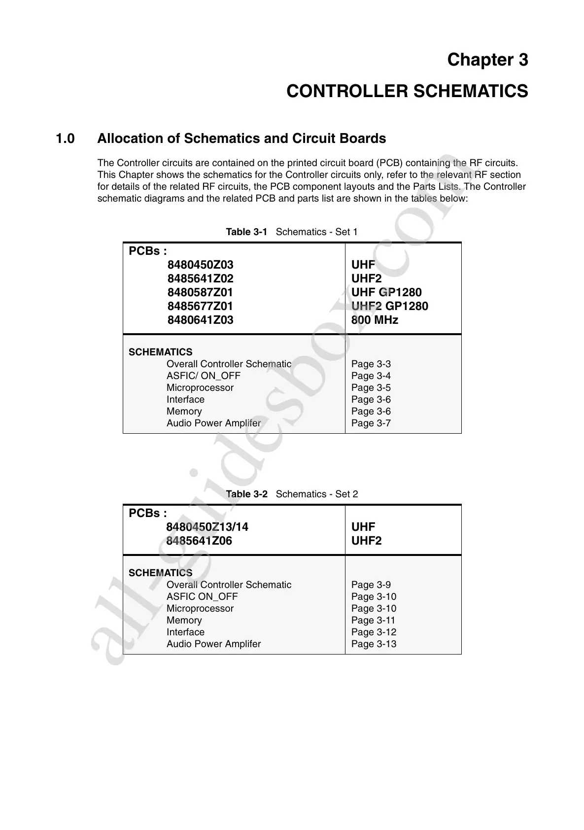
schematic diagrams and the related PCB and parts list are shown in the tables below:
Table 3-1 Schematics - Set 1
PCBs :
8480450Z03
8485641Z02
8480587Z01
8485677Z01
8480641Z03
UHF
UHF2
UHF GP1280
UHF2 GP1280
800 MHz
SCHEMATICS
Overall Controller Schematic
ASFIC/ ON_OFF
Microprocessor
Interface
Memory
Audio Power Amplifer
Page 3-3
Page 3-4
Page 3-5
Page 3-6
Page 3-6
Page 3-7
Table 3-2 Schematics - Set 2
PCBs :
8480450Z13/14
8485641Z06
UHF
UHF2
SCHEMATICS
Overall Controller Schematic
ASFIC ON_OFF
Microprocessor
Memory
Interface
Audio Power Amplifer
Page 3-9
Page 3-10
Page 3-10
Page 3-11
Page 3-12
Page 3-13
All manuals and user guides at all-guidesbox.com
all-guidesbox.com

 Loading...


