5-1
Section 5
KEYPAD BOARD INFORMATION
1.0 Theory of Operation
Keypad
The LED_EN setting is set by the codeplug. When the value is set to high, the LED will not light up
during power up and vice versa.
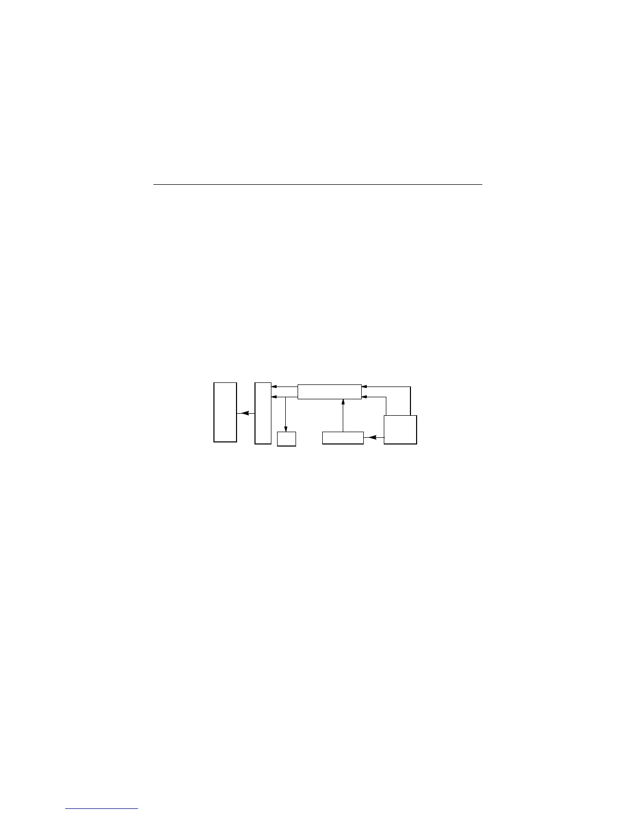
U602 is a comparator that will compare the voltage when any one of the keypad row or keypad
column keys is being pressed. Therefore when a key is being pressed, it will send a message to the
microprocessor through the output (KEY_INT) telling it that a key has been pressed. The
microprocessor will then sample the Analog to Digital voltages at the keypad row and keypad column
and map it with the table so that the key being pressed can be identified. Once the key has been
identified, the message that corresponds to the key will show up at the display.
Figure 5-1: Keypad Block Diagram
40 pin connector
Comparator
Keypad
Button
LED
Display
18 pin connector
Key_Int
Keypad Column
Keypad
Data
Row

 Loading...


