EasyManuals Logo

Motorola GP360 Service Information

Motorola GP360
52 pages
To Next Page IconTo Next Page
To Previous Page IconTo Previous Page
Page #13 background imageLoading...
Page #13 background image
Chapter 3
CONTROLLER SCHEMATICS
1.0 Allocation of Schematics and Circuit Boards
The Controller circuits are contained on the printed circuit board (PCB) containing the RF circuits.
This Chapter shows the schematics for the Controller circuits only, refer to the relevant RF section
for details of the related RF circuits, the PCB component layouts and the Parts Lists. The Controller
schematic diagrams and the related PCB and parts list are shown in the tables below:
Table 3-1 Schematics - Set 1
PCBs :
8486062B12/ B14
8485726Z01
VHF
300 R1
SCHEMATICS
Overall Controller Schematic
ASFIC/ ON_OFF
Microprocessor
Interface
Memory
Audio Power Amplifer
Page 3-5
Page 3-6
Page 3-7
Page 3-8
Page 3-8
Page 3-9
Table 3-2 Schematics - Set 2
PCBs :
8486101B09/ B10 VHF GP1280
SCHEMATICS
Overall Controller Schematic
ASFIC ON_OFF
Memory
Microprocessor
Interface
Audio Power Amplifer
Page 3-11
Page 3-12
Page 3-12
Page 3-13
Page 3-14
Page 3-15/16
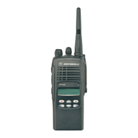
Other manuals for Motorola GP360

Questions and Answers:

Question and Answer IconNeed help?

Do you have a question about the Motorola GP360 and is the answer not in the manual?

Motorola GP360 Specifications

Battery IconBattery
battery life with standard high capacity NiMH battery low power11 hours
battery life with standard high capacity NiMH battery high power8 hours
battery life with ultra high capacity NiMH battery low power14 hours
battery life with ultra high capacity NiMH battery high power11 hours
battery life with NiCD battery low power12 hours
battery life with NiCD battery high power9 hours
battery life with Li-lon low power11 hours
battery life with Li-lon high power8 hours
Operating Environment IconOperating Environment
operating temperature-20°C to +55°C
sealingWithstands rain testing per MIL STD 810 C/D/E and IP54
shock and vibrationProtection via impact resistant housing exceeding MIL STD 810-C/D/E and TIA/EIA 603
dust and humidityProtection via environment resistant housing exceeding MIL STD 810 C/D/E and TIA/EIA 603
Transmitter Specifications IconTransmitter Specifications
frequencies full bandsplit VHF136-174 MHz
frequencies full bandsplit UHF403-470 MHz
channel spacing12.5/20/25 kHz
frequency stability±2.5 ppm
power VHF1-5W
power UHF1-4W
Receiver Specifications IconReceiver Specifications
frequencies full bandsplit VHF136-174 MHz
frequencies full bandsplit UHF403-470 MHz
channel spacing12.5/20/25 kHz
frequency stability±2.5 ppm
sensitivity (12 dB SINAD) EIA0.25 µV typical
sensitivity (20 dB SINAD) EN0.50 µV typical
Weight and Dimensions IconWeight and Dimensions
dimensions with standard high capacity NiMH battery137 x 57.5 x 37.5 mm
dimensions with ultra high capacity NiMH battery137 x 57.5 x 40.0 mm
dimensions with NiCD battery137 x 57.5 x 40.0 mm
dimensions with Li-lon battery137 x 57.5 x 33.0 mm
weight with standard high capacity NiMH battery428 gm
weight with ultra high capacity NiMH battery508 gm
weight with NiCD battery458 gm
weight with Li-lon battery358 gm

Related product manuals