Radio Disassembly — Detailed 3-5
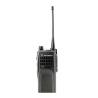
4. Pull the volume and channel selector knobs off of their shafts.
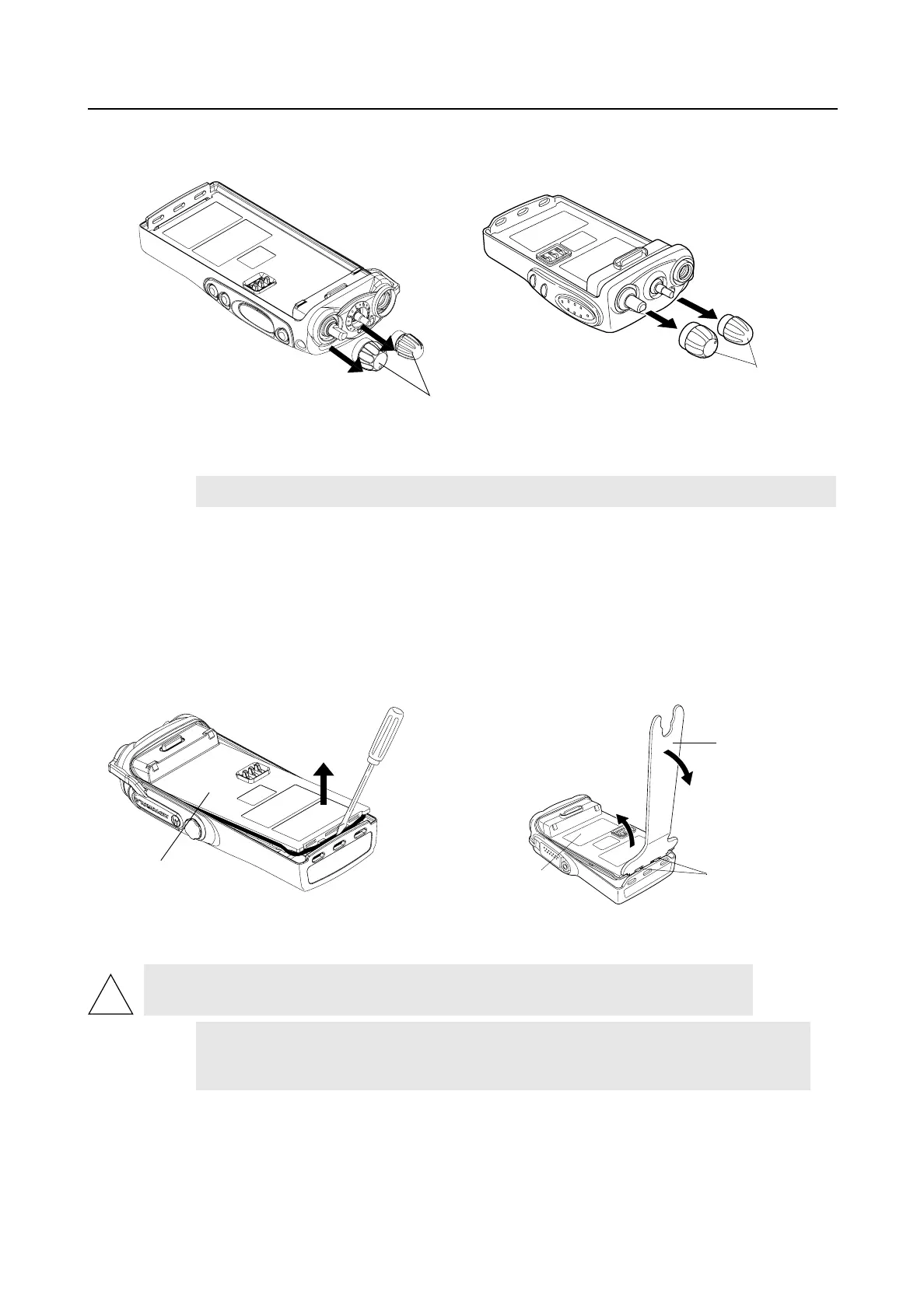
5. Separate the chassis from the internal electronics front cover assembly as follows:
a. Insert a small, flat-blade screwdriver, or similar instrument, in between the thin retaining
wall and the chassis at the bottom of the radio. Do not mar the O-ring sealing area on the
housing.
b. Slowly pry the bottom of the chassis from the cover by pushing the small flat-blade
screwdriver down, or chassis opener (6680702Z01) and rotating the handle of the tool
over and behind the base of the radio. This prying action forces the thin inner plastic wall
toward the base of the radio, releasing the two chassis base tabs.
6. Lay the chassis down. Rotate the front cover backward and slightly away from the chassis.
Figure 3-2 Knob Removal
NOTE
Both knobs slide on and off. However, they are supposed to fit very tightly on their shafts.
Figure 3-3 Chassis Removal
CAUTION: Marring the front cover O-ring sealing area will prevent the radio from
sealing properly.
NOTE
Flexible ribbon circuits (flexes) connecting the front cover assembly and the chassis
prevent you from completely separating the two units. Display radios and radios with
option boards have two flexes.
Knobs
GP320/340/360/380
GP344/388
Knobs
Radio Chassis
Chassis Opener
Chassis Base Tabs
Radio Chassis
GP344/388
GP320/340/360/380
!
 Loading...