4-2 PERFORMANCE TESTING
3.0 Transmitter Performance Tests
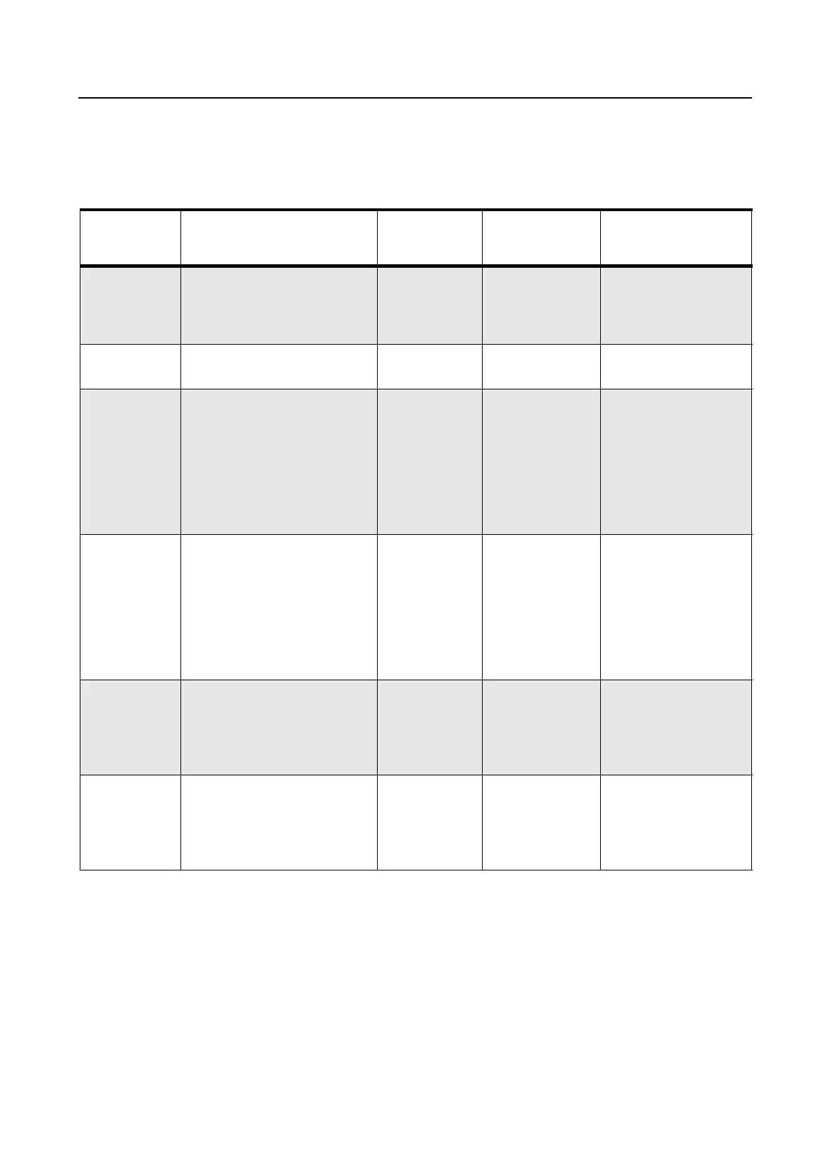
The transmitter performance tests are described in Table 4-2 below.
Table 4-2 Transmitter Performance Checks
Test Name
Communications
Analyzer
Radio Test Set Comments
Reference
Frequency
Mode: PWR MON
Monitor: Frequency error
Input at RF In/Out
TEST MODE,
Test Channel
4 carrier
squelch
PTT to continu-
ous (during the
performance
check)
Frequency error to be
±200Hz VHF
±600Hz UHF
Power RF As above As above As above Refer to Mainte-
nance Specifications
Voice
Modulation
Mode: PWR MON
atten to -70, input to
RF In/Out
Monitor: DVM, AC Volts
Set 1kHz Mod Out level for
0.025Vrms at test set,
80mVrms at AC/DC test set
jack
As above As above, meter
selector to mic
Deviation:
VHF, UHF,
≥ 4.0kHz but
≤ 5.0kHz.
(25 kHz Ch Sp)
Voice
Modulation
(internal)
Mode: PWR MON
atten to -70, input to RF
In/Out
TEST MODE,
Test Channel
4 carrier
squelch
output at
antenna
Remove
modulation
input
Press PTT switch on
radio. Say “four”
loudly into the radio
mic. Measure
deviation: VHF, UHF,
≥ 4.0kHz but
≤ 5.0kHz
(25 kHz Ch Sp)
DTMF
Modulation
As above, TEST MODE,
Test Channel
4 DTMF
output at
antenna
As above Deviation:
VHF, UHF,
≥ 3.05kHz but
≤ 3.45kHz
(25 kHz Ch Sp).
PL/DPL
Modulation
As above
BW to narrow
TEST MODE,
Te st
Channel 4
TPL
DPL
As above Deviation:
VHF, UHF,
≥500Hz but
≤ 1000Hz.
(25 kHz Ch Sp).
 Loading...