iii
Table of Contents
Chapter 1 MODEL CHART AND TECHNICAL SPECIFICATIONS
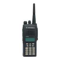
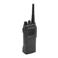
1.0 GP640/GP680 Model Chart .................................................................................1-1
2.0 GP1280 Model Chart ...........................................................................................1-1
3.0 Technical Specifications ......................................................................................1-2
Chapter 2 THEORY OF OPERATION
1.0 Introduction ..........................................................................................................2-1
2.0 UHF2 Transmitter ................................................................................................2-1
2.1 Power Amplifier ..............................................................................................2-1
2.2 Antenna Switch...............................................................................................2-2
2.3 Harmonic Filter ...............................................................................................2-2
2.4 Antenna Matching Network ............................................................................2-2
2.5 Power Control Integrated Circuit (PCIC) ........................................................2-2
3.0 UHF2 Receiver ....................................................................................................2-3
3.1 Receiver Front-End ........................................................................................2-3
3.2 Receiver Back-End.........................................................................................2-4
3.3 Automatic Gain Control (AGC) .......................................................................2-5
4.0 Frequency Generation Circuit ..............................................................................2-6
4.1 Synthesizer.....................................................................................................2-7
4.2 Voltage Control Oscillator (VCO)....................................................................2-8
5.0 Voice Storage (GP1280 Only) ...........................................................................2-10
Chapter 3 TROUBLESHOOTING CHARTS
1.0 Troubleshooting Flow Chart for Receiver (Sheet 1 of 2)......................................3-1
2.0 Troubleshooting Flow Chart for Receiver (Sheet 2 of 2)......................................3-2
3.0 Troubleshooting Flow Chart for Transmitter ........................................................3-3
4.0 Troubleshooting Flow Chart for Synthesizer........................................................3-4
5.0 Troubleshooting Flow Chart for VCO...................................................................3-5
Chapter 4 UHF2 PCB/SCHEMATICS/PARTS LISTS
1.0 Allocation of Schematics and Circuit Boards .......................................................4-1
1.1 Controller Circuits ...........................................................................................4-1
1.2 Voice Storage Facility.....................................................................................4-1
2.0 UHF2 PCB 8485641Z02 / Schematics ................................................................4-3
3.0 UHF2 PCB 8485641Z02 / PCB 8485677Z01 Parts List ...................................4-11
4.0 UHF2 PCB 8485677Z01 (GP1280) ...................................................................4-15
3.0 UHF2 PCB 8485677Z01 / PCB 8485641Z02 Parts List ..................................4-11
5.0 UHF2 PCB 8485677Z01 Voice Storage Parts List (GP1280)............................4-18

 Loading...
