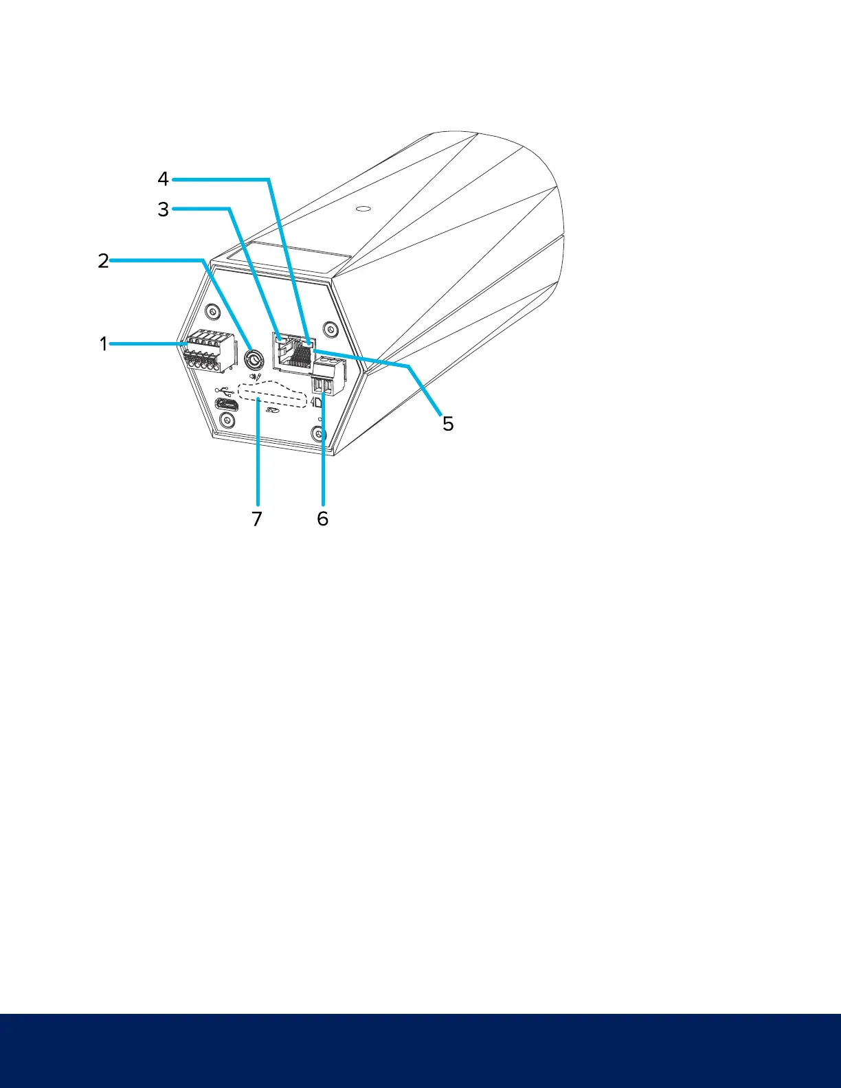
Rear View
1. I/O connector block
Provides connections to external input/output devices.
2. Audio/video connector
Accepts a mini-jack connector (3.5 mm).
3. Connection status LED indicator
Provides information about device operation. For more information, see Connection Status LED Indicator on
page11.
4. Link LED indicator
Indicates if there is an active connection in the Ethernet port.
5. Ethernet port
Accepts an Ethernet connection to a network. Server communication and image data transmission occurs over
this connection. Also receives power when it is connected to a network that provides Power over Ethernet.
6. Power connector block
Accepts a terminal block with either an AC or DC power connection. DC input can be either polarity. Only
Rear View 2
 Loading...