16.8 MHz
data
clock
enab
VCO 4
356.4-368.4 MHz
DIVIDER
/8
frequency range = 352.4-369.4 MHz
resolution step = 10 KHz
frequency range = 44.05-46.15 MH
resolution step = 1.25 KHz
10 KHz
PLL
Figure 5-8. Second Injection Block Diagram
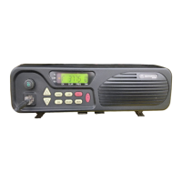
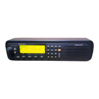
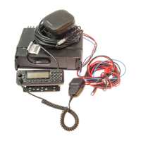
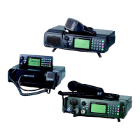
5-5. Electronic Boards
The circuitry of the basic MICOM-3 radio is located on three main boards, as follows:
• Low RF and Digital (LORD) board
• High-Power board
• Control Head board (two versions with similar characteristics are used, one for MICOM-3F and
MICOM-3T, and the other for MICOM-3R).
Note
MICOM-3T also uses an Interconnection board for connection to the Control
Head board.
Figure 5-9 identifies the main boards and Table 5-1 indicates the location of the main radio circuits.
Figure 5-9. Identification of Main MICOM-3 Boards
5-10 Cat. No. 6886859J01
 Loading...