EasyManua.ls Logo

Motorola MICOM-2E ALE - User Manual

Motorola MICOM-2E ALE
132 pages
Print Icon
To Next Page IconTo Next Page
Loading...
MICOM-2E ALE
HF-SSB Transceiver
68P02952C60-O
Owner's Guide

Table of Contents

Other manuals for Motorola MICOM-2E ALE

Questions and Answers

  • T
    thompsonashleyJul 31, 2025
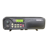
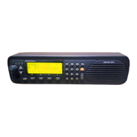
    What to do if my Motorola Transceiver display is on but there's weak or no signal?
    • C
      cmartinJul 31, 2025
      If your Motorola Transceiver shows a display but you are experiencing a weak or nonexistent receive signal or noise, check the connection of the antenna to the antenna tuner and the antenna tuner to the radio cables, ensuring there are no loose or broken connections. Also, verify that the squelch is not in the OFF position and that the operating channel is correctly programmed with the appropriate frequency and mode of operation.
  • C
    campbellrobertAug 12, 2025
    How to stop engine noise on my Motorola MICOM-2E ALE Transceiver antenna?
    • T
      Thomas TaylorAug 12, 2025
      If your Motorola Transceiver picks up engine noise through the antenna, make sure that the ground leads are properly connected, and all power wires and ground leads are as short as possible. Ensure the Noise Blanker (if installed) is enabled. Consider installing a noise reduction Kit TLN8845.
  • T
    Thomas VazquezAug 18, 2025
    What causes low transmitter power on Motorola Transceiver?
    • P
      Patricia CamposAug 18, 2025
      If the RF power bar graph on your Motorola Transceiver is missing bars on the right side, this indicates low transmitter power, which could be due to a faulty microphone, faulty transmitter, overheating, or a defective antenna system.
  • K
    Kristin FosterAug 25, 2025
    How to fix a blank display on a Motorola Transceiver?
    • D
      David GrahamAug 25, 2025
      If your Motorola Transceiver has a blank display, check that the DC power cable is properly connected to both the radio and the battery. Also, verify that a 7.5A fuse is correctly installed in the fuse holder located on the green wire of the DC power cable.
  • H
    halljoseNov 4, 2025
    Why is my Motorola MICOM-2E ALE Transceiver transmission poor or not working?
    • A
      Abigail CookNov 5, 2025
      To address poor or absent transmission on your Motorola Transceiver, ensure a 30A fuse is installed in the fuse holder on the power cable's red wire. Verify that proper grounding cables connect the radio and antenna tuner to the vehicle chassis. While speaking, observe the RF power bars for activity; missing bars on the right indicate low transmitter power. If three or more left-hand bars disappear, there may be a problem in the antenna system. If antenna cabling, antenna mast rigging position has changed since the antenna was last tuned, the antenna tuner will not be adjusted automatically. To retune the antenna tuner, scroll to the next channel and thereafter scroll back. If this procedure does not correct the situation, inspect the tuner, antenna and ground plane for loose connections o...

Summary

Commercial Warranty

Computer Software Copyrights

Glossary

Technical Specifications

General Specifications

Details on frequency range, channel capacity, scanning, frequency stability, dimensions, and operating parameters.

FCC Information

Information regarding FCC emissions, applicable rules, and type acceptance numbers for compliance.

Transmitter Specifications

Performance details of the radio's transmitter, including output power, bandwidth, intermodulation, and emissions.

Receiver Specifications

Performance details of the radio's receiver, including sensitivity, selectivity, image rejection, and noise characteristics.

Military and Industrial Standards

Compliance with various MIL-STD and industry standards for durability, environmental resistance, and performance.

Safe Operation Guidelines

RF Exposure Safety

Guidelines for safe exposure to radio frequency energy and recommended antenna placement for vehicles.

Hazardous Environment Precautions

Safety measures for operating in potentially explosive atmospheres and near blasting caps.

General Safety Warnings and Restrictions

Explains warning symbols, installation safety, operational safety advice, and usage restrictions.

Introduction to the MICOM-2 E

Radio Features and Options

Lists key features and optional accessories for the MICOM-2E radio.

Technical and Operational Aspects

Covers transmitter/receiver features, frequency sources, power, CW keying, and programmable features.

Overview of the MICOM-2 E

Controls, Display, and Indicators

Explains front panel controls, LCD display, icon indicators, and LED indicators.

Rear Panel and Audio Alerts

Details on rear panel connectors and audible alert tones.

Operating Instructions

Radio Activation and Global Operations

Steps to turn on the radio and an overview of controls common to all modes.

Using Working Modes

Introduction to the various operational modes of the MICOM-2E.

Detailed Mode Operations

Explains specific operational modes like Scan, BITE, Lock, Program, Password, Transmit, and DIM.

Programming the MICOM-2 E Radio

Accessing Programming Mode

Steps to enter the radio's programming interface.

Channel Management and Configuration

Procedures for managing channels (GET, STOR, ERAS) and configuring parameters (Tx Power, Freq, Band, Mode, AGC, BW).

Radio Parameter and Option Settings

Configuration of Baud Rate, Data Power, side tones, beeps, time-out, and other radio options.

Automatic Link Establishment (ALE)

Introduction to ALE Functionality

Explanation of ALE, its benefits, and how it improves HF communications.

ALE Activation and Programming

Instructions for enabling/disabling ALE and programming its features.

Sounding and Link Quality Analysis

Details on LQA memory and automatic sounding for channel testing.

Bi-directional Handshake

Procedure for exchanging LQA scores without establishing a full link.

Receiving and Transmitting Calls

How to receive and transmit AllCalls, Individual calls, and Net calls.

Call Management and Monitoring

Using the caller stack, link mode, and monitoring the speaker settings.

Antenna Tuner Operation

Information on configuring and using the automatic antenna tuner for optimal performance.

Radio Installation Guide

General Installation Considerations

Guidelines on regulations, inspection, planning, and mounting location.

Base Station and Vehicle Installation

Instructions for base station setup and vehicle installation (front/trunk models).

Installation Procedures and Connections

Steps for mounting, power connection, microphone clip, final connections, and speaker installation.

Connector Pinouts

Detailed pin connections for microphone, antenna, accessory, and DC connectors.

Vehicular Noise Reduction

Methods and kits to reduce electrical noise interference in vehicles.

Maintenance and Troubleshooting

Maintenance Overview and BITE

Importance of maintenance, using Built-In-Test Equipment (BITE) for diagnostics.

Preventive Maintenance Procedures

Routine checks for system integrity and periodic calibration requirements.

Troubleshooting Guide

User Troubleshooting Chart

A table listing common problems and their corresponding solutions.

Radio Error Messages

Explanations of error messages displayed by the radio during operation.

Service and Support

Motorola Service and Support Information

Details on Motorola's service organization, maintenance agreements, and phone support contacts.

Motorola MICOM-2E ALE Specifications

General IconGeneral
BrandMotorola
ModelMICOM-2E ALE
CategoryTransceiver
LanguageEnglish

Related product manuals