Do you have a question about the Motorola MICOM-3F and is the answer not in the manual?
Standard warranty terms for Motorola radio communications products.
Motorola's rights and restrictions on copyrighted computer programs.
Details general performance parameters like frequency range, impedance, channels, scanning.
Lists weight, current consumption, FCC info, and military/industrial standards.
Details transmitter output power, bandwidth, emissions, and receiver sensitivity.
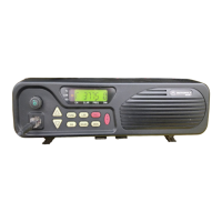
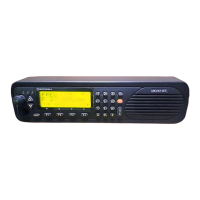
Lists radio controls and other technical specifications like RGC range.
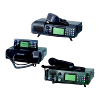
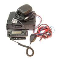
Lists parts, operating options, and mobile accessories for the MICOM-3F model.
Lists parts, operating options, and mobile accessories for the MICOM-3T model.
Lists operating options and accessories for the MICOM-3R, including military audio.
Lists service manuals, retrofit kits, and spare boards for the MICOM-3 series.
Details the 4-year extended warranty offering for MICOM-3F and other models.
Explains notations and defines the manual's scope and intended audience.
Details FCC rules, exposure limits, and installation guidelines for radios.
Covers warnings for hazardous environments and safe handling of sensitive components.
Lists standard test equipment needed for servicing the radios.
Provides lists of spare part kits and components for MICOM-3 models.
Covers general procedures and torque specifications for component handling.
Details steps for disassembling the MICOM-3, including control head and boards.
Provides step-by-step instructions for reassembling the radio components.
Lists the three required calibrations: transmitter, power, and oscillator.
Details transmitter, power, and oscillator calibration steps, referencing RSS manual.
Introduces radio operation and explains the transmitter's signal path and DSP processing.
Explains the receiver's function, conversion stages, and gain control.
Describes the synthesizer's design and the main electronic boards (LORD, High-Power).
Outlines the troubleshooting approach and indicates the availability of charts.
Provides a flowchart for diagnosing and resolving receiver-related problems.
Offers a flowchart for diagnosing and resolving transmitter-related problems.
Includes detailed schematic diagrams for the LORD board's RF, CPU, and Audio sections.
Provides schematics for the Harmonic Filter, DC Regulators, Power Amplifier, and Drivers.
Details schematics for the Host, LCD, RS-232, USB, Power Supply, Audio, and Keypad sections.
| Antenna Impedance | 50 Ohms |
|---|---|
| Type | Transceiver |
| Frequency Range | 1.6 - 30 MHz |
| Power Output | 25 W |
| Channels | 100 |
| Output Power | 25 W |