PIN Function Description
25 IGNITION Ignition input (through
series 15K) – Pull > 10
V to power on
26 EXTERNAL ALARM External Alarm output
(Pulled via 4K7 to A+)
CAUTION: PIN 25: If the ignition line is not used, it must be grounded for example connected to
pin 8. Interference can cause radio to hang.
NOTICE: PINs 13 and 15 cannot be used (nor configured) at the same time.
5.2
Accessory Connection Plan
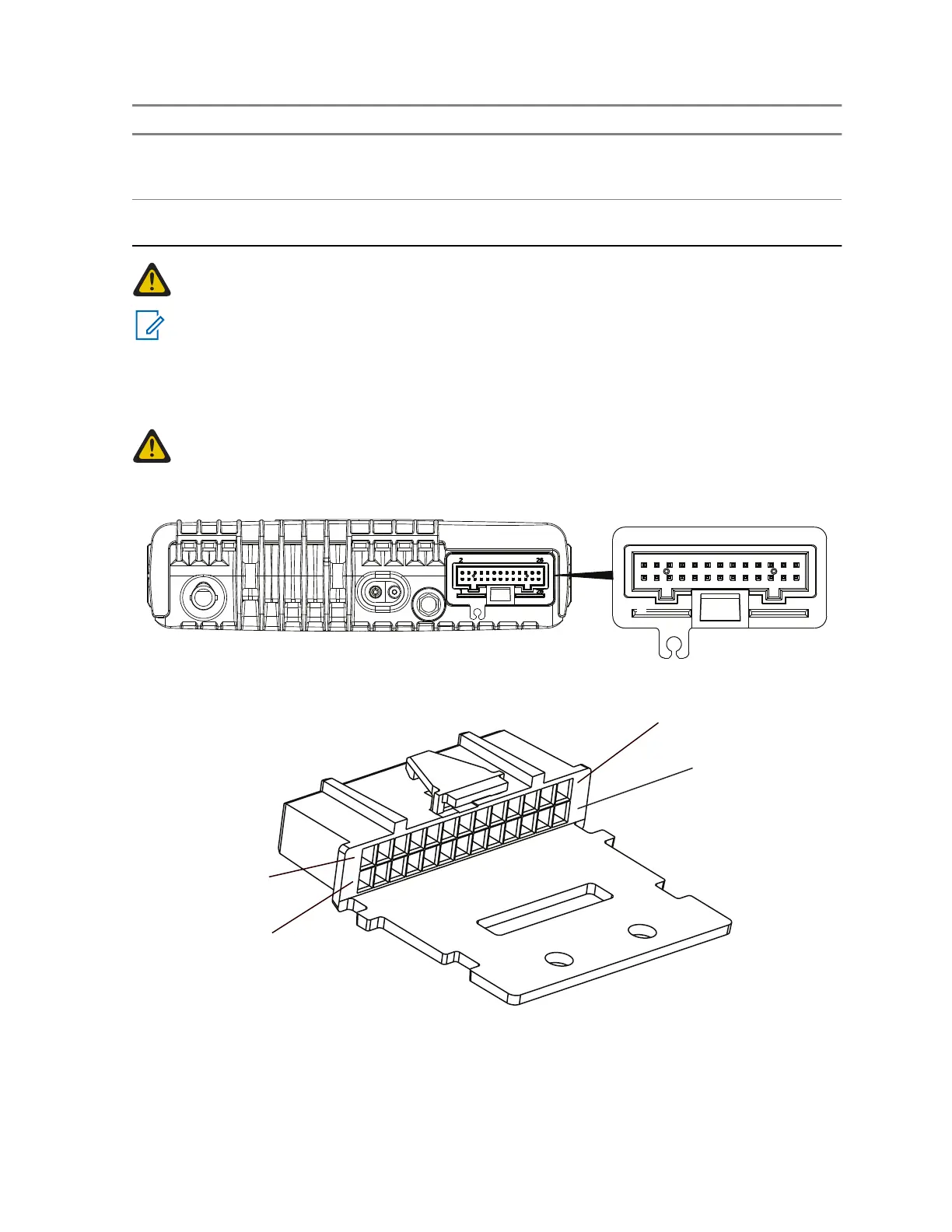
CAUTION: The accessory connections shown are not compatible to some other models of
Motorola radios. Check the appropriate accessory or technical manual for further information.
Ensure correct position of the accessory connector.
Figure 54: Accessory Connector
Figure 55: 26–Pin Accessory Connector
The 26-pin connector, Part Number: 1516174H01 (delivered with the accessory connector kit, Part
Number: PMLN5072_) plugs into the 26-pin accessory connector on the terminal.
68015000181-LB
Chapter 5: Connectors and PIN Assignment
Send Feedback 95
 Loading...