English
m
XPR Series Digital
Portable Radios
Quick Reference Card
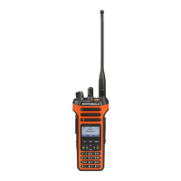
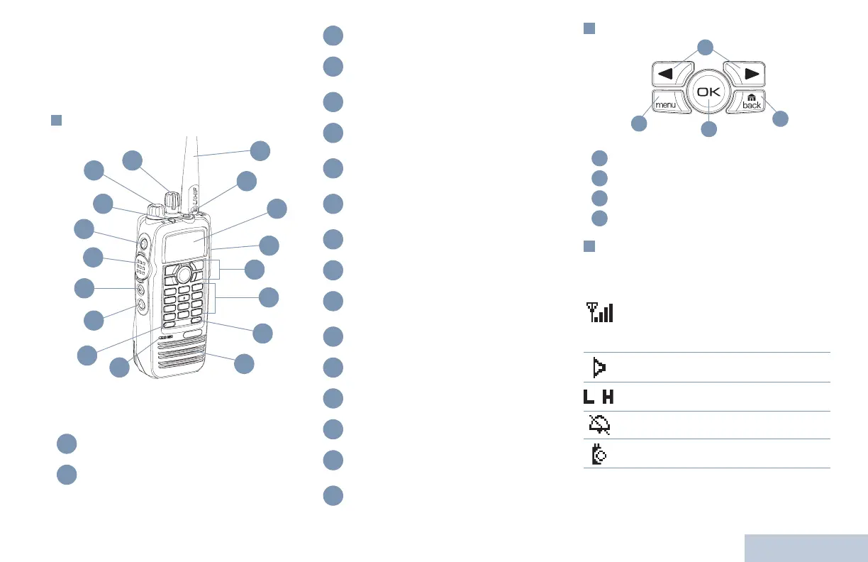
Radio Controls
Record your radio’s programmable button
functions in the blanks provided. SP represents
Short Press, LP represents Long Press.
Menu Navigation Buttons
Display Icons
The following are the icons that appear on the
radio’s display.
Channel Selector Knob
On/Off/Volume Control Knob
7
6
5
4
2
13
14
15
16
1
9
11
12
17
3
8
10
1
2
LED Indicator
Side Button 1 (Programmable)
SP: _____________ LP: _____________
Push-to-Talk (PTT) Button
Side Button 2 (Programmable)
SP: _____________ LP: _____________
Side Button 3 (Programmable)
SP: _____________ LP: _____________
Front Button P1 (Programmable)
SP: _____________ LP: _____________
Microphone
Speaker
Front Button P2 (Programmable)
SP: _____________ LP: _____________
Keypad
Menu Navigation Keys
Universal Connector for Accessories
Display
Emergency Button (Programmable)
SP: _____________ LP: _____________
Antenna
3
4
5
6
7
8
9
10
11
12
13
14
15
16
17
Left/Right Navigation Keys
Menu Button
OK Button
Back/Home Button
The number of bars displayed represents
the radio signal strength. Four bars
indicates the strongest signal. This icon is
only displayed while receiving.
Selected channel is being monitored.
Radio is currently set at Low Power (L) or
High Power (H).
Tones are turned off.
The Option Board is enabled.
A
B
C
D
A
B
C
D
or
© 2006 – 2008 by Motorola, Inc. All Rights Reserved. 04/08
1301 E. Algonquin Rd., Schaumburg, IL 60196-1078, U.S.A.
Printed in the U.S.A.
*6880309T13*
6880309T13-D
NAG-LACR-EMEA.book Page 69 Monday, April 28, 2008 4:59 PM
 Loading...