Do you have a question about the Motorola XPR 7550e and is the answer not in the manual?
Ensures safe usage of the product and compliance with RF exposure guidelines.
Details TIA 4950 certification and classification for intrinsically safe radios.
Provides information on warranty, liability, and product changes.
Details the warranty coverage and duration for Motorola communication products.
Explains the use of notes, cautions, and warnings in the manual.
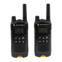
Provides an overview of the XPR 7000e series radio features and design.
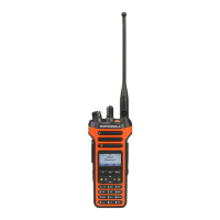
Details the components and features of the full keypad radio model.
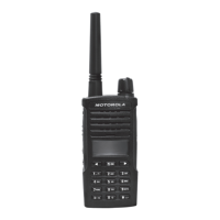
Details the components and features of the non-keypad radio model.
Explains the structure and meaning of the radio's model numbering.
Presents charts detailing VHF, UHF, and 800/900 MHz radio models and accessories.
Lists technical specifications including frequency, dimensions, and battery life.
Lists essential test equipment required for servicing Motorola portable radios.
Lists recommended service aids and tools for radio maintenance and testing.
Overview of performance testing standards and accuracy requirements.
Describes the required setup and initial control settings for performance testing.
Procedures for entering and navigating test modes on display-equipped radios.
Enables testing and alignment by removing the radio from normal operating environment.
Tests the functionality of the radio's LED indicators.
Tests the accelerometer function by checking its response.
Tests the LCD and keypad backlight functionality.
Tests the internal speaker by generating a 1 KHz tone.
Tests the earpiece by generating a 1 KHz tone.
Routes external mic audio to the earpiece for testing.
Displays the battery's remaining capacity percentage.
Tests the functionality of all buttons, knobs, and the PTT switch.
Procedures for entering and navigating test modes on non-display radios.
Overview of Customer Programming Software (CPS) and related applications.
Guides through the setup process for programming the radio using CPS.
Details the AirTracer tool for capturing radio traffic and error logs.
Describes the setup required for tuning the radio with PC and test equipment.
Instructions for assembling the RF adaptor for radio testing.
Overview of maintenance, handling, disassembly, and repair procedures.
Covers periodic inspection and cleaning of the radio.
Precautions for handling static-sensitive components during service.
General guidelines for repair, including solder types and circuit board handling.
General steps and tools required for radio disassembly and reassembly.
Step-by-step instructions for disassembling the radio's components.
Detailed steps for disassembling the radio's chassis and mainboard.
Instructions for removing the interface, keypad, and LCD boards.
Steps for removing the speaker and universal connector flex circuits.
Procedure for removing the emergency button assembly.
Instructions for removing the Bluetooth GPS antenna module.
Step-by-step instructions for reassembling the radio's components.
Instructions for reassembling the speaker and universal connector flex.
Steps for reassembling the interface, keypad, and LCD boards.
Detailed steps for reassembling the radio's chassis.
Instructions for reassembling the chassis and front cover.
Discusses tests, disassembly, and reassembly for radio immersibility.
Procedure for replacing the battery contact seal.
Procedure for replacing the air ventilation label.
Recommendations for cleaning and maintaining battery contacts.
Flow charts for troubleshooting vacuum and pressure test failures.
Provides exploded views and parts lists for radio components.
Covers error codes and board replacement procedures for troubleshooting.
Steps for installing replacement kits after isolating a problem to a specific board.
Lists and explains power-up error codes and their corrective actions.
Lists and explains operational error codes detected during radio use.
Lists approved accessories to enhance radio productivity.
Details available battery options for the portable radios.
Lists various antenna types compatible with the radio models.
Presents options for carrying the radio, such as cases and belt clips.
Identifies the Customer Programming Software (CPS) part number.
Lists other accessories like option boards.
Guidance on ordering replacement parts and product information.
Information on accessing the online catalog for parts and products.
Information on identifying and locating parts through Motorola.
Contact information for customer service regarding radio products.
Guidance on when to send radios to Motorola Service Centers.
References maintenance procedures from Chapter 5.
Procedures for replacing chip components using hot-air or soldering iron.
Lists components and their references on the PCB.
| Channel Capacity | 1000 channels |
|---|---|
| IP Rating | IP68 |
| Power Output | VHF: 1-5W, UHF: 1-4W |
| Digital Protocol | DMR |
| Bluetooth | Yes |
| GPS | Yes |
| Frequency Range | VHF: 136-174 MHz |
| Display | Full color 5-line display |
| Dimensions | 5.1 x 2.2 x 1.4 in (130 x 55 x 36 mm) |