List of Figures xi
List of Figures
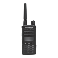
Figure 1-1. Full Keypad Model ............................................................................................................... 1-2
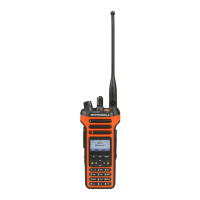
Figure 1-2. Non Keypad Model............................................................................................................... 1-4
Figure 1-3. Portable Radio Model Numbering Scheme.......................................................................... 1-5
Figure 2-1. Programming, Testing and Alignment Cable........................................................................ 2-3
Figure 2-2. Pin Layout of Side Connector .............................................................................................. 2-4
Figure 3-1. DMR Radio Transmitter and Receiver Testing Setup .......................................................... 3-3
Figure 3-2. Battery Check Test Mode Display ......................................................................................3-11
Figure 4-1. CPS Programming Setup..................................................................................................... 4-1
Figure 4-2. Radio Tuning Equipment Setup ........................................................................................... 4-2
Figure 4-3. RF Plug removal .................................................................................................................. 4-3
Figure 4-4. RF Adaptor holder................................................................................................................ 4-3
Figure 4-5. RF Adaptor screw ................................................................................................................ 4-4
Figure 4-6. RF Adaptor complete assembly........................................................................................... 4-4
Figure 5-1. Battery removal.................................................................................................................... 5-6
Figure 5-2. Antenna removal.................................................................................................................. 5-6
Figure 5-3. Shroud removal.................................................................................................................... 5-7
Figure 5-4. Chassis removal .................................................................................................................. 5-7
Figure 5-5. Chassis and Front Housing.................................................................................................. 5-8
Figure 5-6. Keypad flex removal............................................................................................................. 5-8
Figure 5-7. Interface flex removal........................................................................................................... 5-9
Figure 5-8. GOB and mini GOB flex removal ....................................................................................... 5-10
Figure 5-9. Mainboard removal ............................................................................................................ 5-10
Figure 5-10. Top control seal removal .................................................................................................... 5-11
Figure 5-11. GOB removal ..................................................................................................................... 5-11
Figure 5-12. Battery contact seal removal.............................................................................................. 5-12
Figure 5-13. RF rubber plug removal ..................................................................................................... 5-12
Figure 5-14. Interface flex removal......................................................................................................... 5-14
Figure 5-15. UC flex removal ................................................................................................................. 5-14
Figure 5-16. PTT flex removal................................................................................................................ 5-15
Figure 5-17. Interface board removal ..................................................................................................... 5-15
Figure 5-18. Keypad board removal....................................................................................................... 5-16
Figure 5-19. Display module removal..................................................................................................... 5-16
Figure 5-20. UC escutcheon removal..................................................................................................... 5-17
Figure 5-21. UC flex removal ................................................................................................................. 5-17
Figure 5-22. Speaker assembly removal................................................................................................ 5-18
Figure 5-23. Speaker removal................................................................................................................ 5-18
Figure 5-24. Emergency button removal ................................................................................................ 5-19
Figure 5-25. Bluetooth GPS antenna removal .......................................................................................5-20
Figure 5-26. Bluetooth GPS antenna reassembly.................................................................................. 5-21
Figure 5-27. Emergency button reassembly
...
........................................................................................ 5-21
Figure 5-28. Speaker retainer reassembly ............................................................................................. 5-22
Figure 5-29. Speaker reassembly .......................................................................................................... 5-22
Figure 5-30. UC Escutcheon replacement ............................................................................................. 5-23
Figure 5-31. Display module reassembly ............................................................................................... 5-24
Figure 5-32. Keypad Board reassembly................................................................................................. 5-24
Figure 5-33. Front housing reassembly.................................................................................................. 5-25
Figure 5-34. Chassis reassembly........................................................................................................... 5-26
Figure 5-35. Thermal Pad ...................................................................................................................... 5-26
Figure 5-36. Top control seal reassembly............................................................................................... 5-27
Figure 5-37. Main board and GOB reassembly...................................................................................... 5-28

 Loading...


