1-2 Introduction: Radio Description
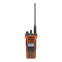
1.2.1 Full Keypad Model
Figure 1-1. Full Keypad Model
• ON/OFF/VOLUME KNOB – Rotate clockwise until click is heard to turn on radio; rotate counter-
clockwise until click is heard to turn off radio. Rotate clockwise to increase volume level; rotate
counter-clockwise to decrease volume level.
• LED INDICATORS – Red, green and orange light-emitting diodes indicate operating status.
• LCD (Liquid Crystal Display):
- 132x90 highly transflective color display provides visual information about many radio
features.
• MENU NAVIGATION KEYS – Five keys to provide menu navigation and selection interface.
• KEYPAD – Twelve keys that allows the user to input characters for various text based
operations. (For color display only)
• FRONT BUTTONS and SIDE BUTTONS – These five buttons are field programmable using the
CPS.
• CHANNEL SELECTOR KNOB – Rotate clockwise to increment and counter clockwise to
decrement the channel.
• PUSH-TO-TALK (PTT) – Press to execute voice operations (e.g. Group call and Private Call).
• ANTENNA – Provides the needed RF amplification when transmitting or receiving.
• MICROPHONE – Allows the voice to be sent when PTT or voice operations are activated.
• UNIVERSAL CONNECTOR FOR ACCESSORIES – Interface point for all accessories to be
used with the radio. It has twelve points to which specific accessories will connect and be
activated.
• EMERGENCY BUTTON – Turns on and off the Emergency Operations.
Antenna
Channel Selector Knob
On/Off Volume Control Knob
LED Indicator
PTT Button
Side Button 1
Side Button 3
Emergency Button
Speaker
LCD
Keypad
Menu Navigation Key
Side Button 2
Universal
Microphone
Front Buttons
Connector
 Loading...