- 4 -
Hardware Installation Procedure
STEP 1: After removing the MGate MB3170/3270 from the box, connect
the MGate MB3170/3270 to a network. Use a standard straight-through
Ethernet (fiber) cable to connect the unit to a hub or switch. When setting
up or testing the MGate MB3170/3270, you might find it convenient to
connect directly to your computer’s Ethernet port. In this case, use a
crossover Ethernet cable.
STEP 2: Connect the serial port(s) of the MGate MB3170/3270 to a serial
device.
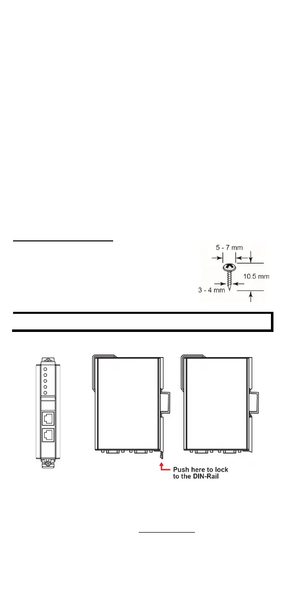
STEP 3: The MGate MB3170/3270 is designed to be attached to a DIN rail
or mounted on a wall. The two sliders on the MGate MB3170/3270 rear
panel serve a dual purpose. For wall mounting, both sliders should be
extended. For DIN-rail mounting, start with one slider pushed in, and the
other slider extended. After attaching the MGate MB3170/3270 on the
DIN rail, push the extended slider in to lock the device server to the rail.
The two placement options are illustrated in the accompanying figures.
STEP 4: Connect the 12 to 48 VDC power source to terminal block power
input.
Wall or Cabinet Mounting
Mounting the MGate MB3170/3270 Series on to a
wall requires
two screws. The heads of the screws
to 7 mm in diameter, the shafts should
to 4 mm in diameter, and the length of the
screws should be more than 10.5 mm.
Wall mounting is certified for use in maritime applications.
Wallmount DIN Rail
Software Installation Information
ou can download the MGate Manager, User's Manual, and Device Search
Utility (DSU) from Moxa's website: www.moxa.com
. Please refer to the
User’s Manual for additional details on using the MGate Manager and
DSU.

 Loading...