— 1 — — 2 — — 3 —
NPort 5600-8-DT Series
Quick Installation Guide
Second Edition, December 2008
1. Overview
The following models comprise the NPort 5600-8-DT Series:
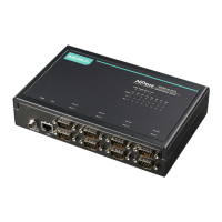
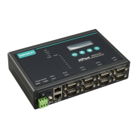
NPort 5610-8-DT: 8 ports, RS-232, DB9
NPort 5610-8-DT-J: 8 ports, RS-232, RJ45
NPort 5650-8-DT: 8 ports, RS-232/422/485, DB9
NPort 5650-8-DT-J: 8 ports, RS-232/422/485, RJ45
NPort 5650I-8-DT: 8 ports, RS-232/422/485, DB9, optical isolation.
2. Package Checklist
The NPort 5600-8-DT package should contain the following items:
y NPort 5600-8-DT 8-port serial device server
y NPort Document & Software CD
y NPort 5600-8-DT Quick Installation Guide
y Power cord and adaptor
y DIN-rail kit
Optional Accessories:
y DK-35A: DIN-rail mounting kit (35 mm)
y CBL-RJ45M9-150: 8-pin RJ45 to male DB9 cable, 150 cm
y CBL-RJ45F9-150: 8-pin RJ45 to female DB9 cable, 150 cm
y CBL-RJ45M25-150: 8-pin RJ45 to male DB25 cable, 150 cm
y CBL-RJ45F25-150: 8-pin RJ45 to female DB25 cable, 150 cm
y NP21101: DB25-M to DB9-F RS-232 cable, 30 cm
Please notify your sales representative if any of the above items are
missing or damaged.
3. Hardware Introduction
Top and Rear View
Port 7
Port 8
Port 5
Port 6
Port 3
Port 4
Port 1
Port 2
Reset
Console
LCM display panel
Input buttons
Indicator LEDs
RS-232 Console port
Reset button
Front View (NPort 5610-8-DT, 5650-8-DT, 5650I-8-DT)
V+
V-
ETH1
12-48 VDC
Port 7
Port 8
Port 5
Port 6
Port 3
Port 4
Port 1
Port 2
LAN
ETH2
Male DB9 serial ports
Power input
RJ45 10/100 Mbps Ethernet ports
Terminal Block power input
Power switch
Front View (NPort 5610-8-DT-J, 5650-8-DT-J)
V+
V-
12-48 VDC
LAN
RJ45 Serial ports
Power input
RJ45 10/100 Mbps Ethernet ports
Terminal Block power input
ETH2
ETH1
Serial Ports
1 2 3 4 5 6 7 8
Power switch
Reset Button
The reset button is used to load the factory defaults. Use a pointed object
to hold the reset button down for five seconds. You may release the reset
button when the Ready LED stops blinking.
LED Indicators
The LED indicators on the top panel are used to display status as follows:
Name Color Function
red Power is on.
PWR
off Power is off.
green Steady: NPort is operational
Blinking: NPort is responding to NPort
Administrator “Locate” function
Ready
off Power is off or fault condition exists.
red IP conflict or DHCP or BOOTP server did not
respond properly.
Fault
off No fault condition detected.
green Steady: Network is connected, no data is
being transmitted.
Blinking: Network is connected, data is
being transmitted.
Link
off Ethernet cable is disconnected or has a short.
green Serial port has been opened by server side
software.
InUse
(P1 to P8)
off Serial port is not currently opened by server side
software.
green (Tx) Serial device is transmitting data.
orange (Rx) Serial device is receiving data.
Tx/Rx
(P1 to P8)
off No data is flowing to or from the serial port.
4. Hardware Installation
STEP 1: After removing the NPort 5600-8-DT from the box, place it on a
desktop or other horizontal surface. Connect the 12-48 VDC power
adaptor to the NPort 5600-8-DT’s power input when using an AC power
source, or connect the NPort 5600-8-DT’s terminal block directly to a DC
power source.
STEP 2: Use an Ethernet cable to connect the NPort 5600-8-DT to a
network hub or switch. You can also connect directly to your computer’s
Ethernet port, which is convenient for initial configuration or testing.
STEP 3: Connect the NPort 5600-8-DT’s serial port to a serial device.
Wall or Cabinet Mounting
The NPort 5600-8-DT comes with two metal attachment plates to allow
installation on a wall or the inside of a cabinet. First, attach the brackets
to the back of the NPort with screws. Next, mount the unit on a wall or
cabinet with screws. Screws should be less than 6.0 mm in head diameter,
and less than 3.5 mm in shaft diameter.
7 t
r
o
P
8
t
roP
5 t
roP
6 tr
o
P
3
t
roP
4 troP
1
t
roP
2
troP
mm 0.6
mm 5.3
DIN-Rail Mounting
DIN-rail attachments can be purchased separately to attach the product to
a DIN-rail. The DIN-rail attachments should be oriented with the metal
springs on top.
Standard Attachment
Termination Resistor for the RS-485 Port
DK-35A Attachment
7 troP
8
t
roP
5
t
roP
6 tro
P
3
t
roP
4 troP
1 tr
o
P
2
t
roP
P/N: 1802056001011