– 1 – – 2 – – 3 –
P/N: 1802066500013
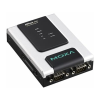
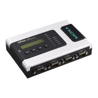
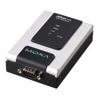
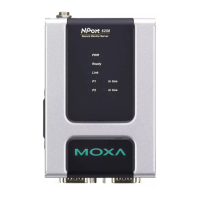
NPort 6600 Series
Quick Installation Guide
Fifth Edition, March 2011
1. Overview
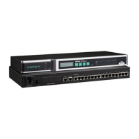
The NPort 6600 series of serial device servers includes 8-port,
16-port, and 32-port models for connecting larger numbers of
serial devices to Ethernet. Some applications now also require
better security when transmitting data through a network. The
NPort 6600 series of device servers use DES, 3DES, and AES data
encryption to provide secure network communication.
2. Package Checklist
Before Installing your NPort 6600 series secure device server,
verify that the package contains the following items:
• 1 NPort 6600 device server
• CBL-RJ45M9-150: 8-pin RJ45 to DB9 male connection cable,
150 cm
• Power Cord (AC models only)
• 2 rack-mount ears
• Documentation and software CD
• Quick installation guide (printed)
• Warranty card
Optional Accessories
• DK-35A: 35 mm DIN-Rail Mounting Kit
• DIN-Rail Power Supply
• NM-TX01/NM-TX01-T: Network module with one
10/100BaseTX Ethernet port (RJ45 connector; supports
cascade redundancy)
• NM-FX01-S-SC/NM-FX01-S-SC-T: Network module with one
100BaseFX single mode fiber port (SC connector; supports
cascade redundancy)
• NM-FX02-S-SC/NM-FX02-S-SC-T: Network module with two
100BaseFX single mode fiber ports (SC connectors; supports
cascade redundancy)
• NM-FX01-M-SC/NM-FX01-M-SC-T: Network module with one
100BaseFX multi mode fiber port (SC connector; supports
cascade redundancy)
• NM-FX02-M-SC/NM-FX02-M-SC-T: Network module with two
100BaseFX multi mode fiber ports (SC connectors; supports
cascade redundancy)
• NM-GPRS/GSM: GPRS/GSM modem module
• NM-Modem/NM-Modem-T: One PSTN modem port with RJ11
connector
NOTE: Please notify your sales representative if any of the above
items is missing or damaged.
3. Hardware Introduction
Demonstrated 8 port model to be an example.
Reset button
Press the Reset button continuously for 5 sec to load factory
defaults
Adjustable pull high/low resistor for RS-485 (150 KΩ or 1
K
Ω)
The NPort 6650 has 3 DIP Switches associated with each serial port
for configuring the pull high/low resistors for RS-485 applications.
The switches are located in a recess on the bottom of the NPort
6650. To access the switches, first remove the panel covering the
recess.
: Use a pointed object to press the reset button. Release
the button after the Ready LED stops blinking.
SW 1 2 3
Pull High Pull Low Terminator
ON 1 KΩ 1 KΩ 120 KΩ
not responding, or relay output.
Check relay output first. If still
blinking, then there is an IP
conflict, or the DHCP or BOOTP
server did not respond properly.
Green Steady
on:
Power is on and the NPort 6600
series is functioning normally.
Blinking:
port.
FX Orange Steady on: Ethernet fiber connection,
but port is idle.
Blinking: Fiber port is transmitting or
receiving data.
P1-P16
in-use
LEDs
Green Serial port is opened by server side
software.
Off Serial port is not opened by server side
software.
Alarm Red The relay Dout is open (exception)
Off The relay Dout is Shorted (normal)
Module Green Network module is plugged in and detected
Off No module present
GSM Green GSM Connection
GPRS Orange GPRS Connection
GPRS/GSM
Signal
Strength
Green More LEDs indicates better signal; 4 LEDs
indicates maximum signal strength.