5
3. Remove top half of stator support (1700).
4. Unbolt stator clamp ring (1800) from suction
housing, remove stator from rotor, turning stator while
removing will ease disassembly. Use a screwdriver tip
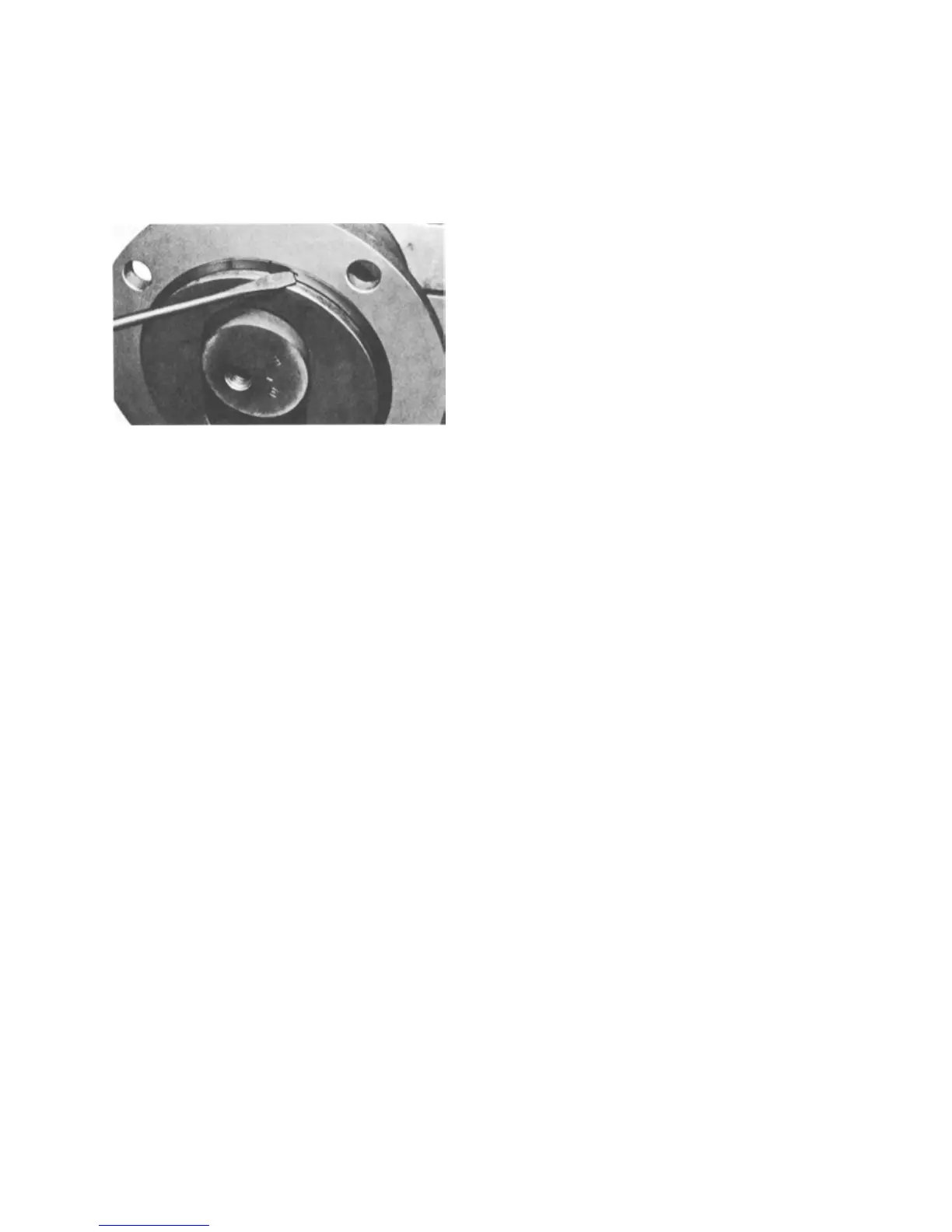
to carefully remove the stator retaining ring. Remove
stator clamp ring (1800) from stator (6500). See Figure
4-3 for the typical retaining ring removal procedure.
Figure 4-3. Typical Retaining Ring Removal
Note: On some four-stage models, a stator adaptor
(1500) and gasket (1210) will be installed
between the stator and suction chamber.
4-10. Suction Chamber Removal
1. On standard and close-coupled models, remove
four suction chamber bolts and lock washers (M)
holding suction chamber to bearing housing (0100). On
open throat models, studs (O) screwed into the bearing
housing are used in place of the suction chamber bolts.
Remove four suction chamber nuts and lock washers
(O) holding suction chamber to bearing housing.
Remove stator gasket from housing.
2. Remove suction chamber and suction chamber
gasket (1220) over the connecting rod (6200) and rotor
on standard models or auger assembly (6200) and rotor
on open throat models.
4-11. Rotor Removal
1. With snap ring pliers, remove the rotor head snap
ring (J), sliding it down over the rotor. Some models
may use spiral type rings (see Figure 4-3).
2. Carefully tap the retaining ring (6100) towards the
rotor end exposing the edge of the universal joint seal
(6400).
3. Remove the edge of the universal joint seal from
the groove in the rotor head and fold the seal back.
4. Carefully tap the retaining ring back towards the
universal joint seal until the drive pin (6300) is exposed.
5. Push the drive pin through the rotor head and
remove the rotor.
6. Remove head O-ring (K) from rotor head.
4-12. Connecting Rod or Auger Assembly Removal
1. Remove the drive shaft head snap ring (J) sliding it
back towards the bearing housing. Some models may have
spiral type rings (see Figure 4-3).
2. Tap the retaining ring towards the bearing housing,
exposing the edge of the universal joint seal.
3. Remove the edge of the universal joint seal from the
groove and fold the seal back.
4. Slide the retaining ring back towards the seal until the
drive pin is exposed.
5. Push the drive pin through the drive shaft head and
remove the connecting rod or auger assembly from the
drive shaft (6000).
6. Remove head O-ring from drive shaft head.
4-13. Packing Removal
To remove packing without removing the drive shaft and
bearing assembly, refer to Section 4-4. If the drive shaft
and bearing assembly are to be removed, proceed directly
to Sections 4-14 and 4-15.
4-14. Drive Shaft Removal
Shaft Drive Models (one-piece shaft, not close-coupled)
The Moyno 1000 pump is designed so that the stuffing
box (1000), packing gland, packing, and bearings (D or E)
are removed as an assembly with the drive shaft. For
Close-Coupled models, skip to Step 17. For two-piece
Shaft Drive models, skip to Step 6.
1. Remove the drive shaft key (I).
2. Remove bearing cover screws and lock washers (A).
Note: Ball bearing models do not have a bearing cover. A
bearing housing snap ring (G), located at the drive
shaft end of the bearing housing, is used to position
the drive shaft and bearings. This snap ring need not
be removed.
3. Slide bearing cover (0300) with grease seal (B) and
bearing shims (6700) off of drive shaft.
4. Using snap ring pliers, remove the bearing housing
snap ring (G) located at the stuffing box end of the bearing
housing.
5. Slide drive shaft assembly from bearing housing.
Shaft Drive Models (two-piece shaft, not close-coupled)
The Moyno 1000 pump is designed with a two-piece drive
shaft available that allows for removal of the drive shaft
head for easy seal maintenance.
6. Remove drive shaft key (I).
7. Move slinger/pin retainer (6800) toward packing or seal
housing, exposing shaft pin.
 Loading...