4-19. Torque Limiter Removal
1. Complete Section 4-17, steps 1-3.
2. Complete Section 4-18, steps 1-3.
3. Loosen set screw on torque limiter (3), and remove key
from shaft (17). Pull torque limiter (3) and sprocket (4) from
shaft (17).
4-20. Shaft Gears Removal
1. Complete Section 4-17, steps 1-3.
2. Complete Section 4-18, steps 1-3.
3. Loosen set screws on drive sprocket (33) and remove.
4. Remove two bolts attaching chain cover (5) to the
pump body.
5. Remove four screws (A) that hold gear cover (8) in po-
sition. Remove screws (B) that attach oil tray (12) to gear
cover (8). Separate these parts and remove.
6. Remove bolts (C) and lockwashers (D) that attach
bearing support (11) to the pump body.
7. Loosen set screws on two sets of bearings (27) located
toward drive end of pump.
8. Slide entire assembly, consisting of shafts No. 1 and
No. 3 (17 and 18), gears (16), bearing support (11), etc. to-
ward drive end of pump and away from suction flange (31).
9. Loosen bolts on gears (16), and remove keys (M) in
order to slide gears (16) off the shafts (17 and 18).
4.21. Breaker End Shafts or Paddle Assembly Removal
1. Complete Section 4-17.
2. Remove guard (19).
3. Loosen set screws on bearings (27) at discharge end
of pump. Unbolt bearing retainer (28) from suction flange
(31). Pull bearing retainer (28) from shafts (22). Remove
spacer (30), and pull shafts (22) out of stuffing boxes and
paddle assemblies (21).
4. Pull paddle assemblies (21) toward discharge end of
pump to free from drive shafts (17 and 18).
4-22. Drive Assembly Shafts Removal
1. Complete Section 4-17, steps 1-3.
2. Complete Section 4-18, steps 1-3.
3. Complete Section 4-19.
4. Complete Section 4-20.
5. Remove bearing cover plate (6).
6. Loosen set screws on both flange block bearings (10).
Page 7
7. Pull both shafts (17 and 18) from bearings (10) and
bearing support (11).
4-23. Packing Removal
1. Complete section 4-17.
2. Remover oiler (1) nearest discharge end of pump.
3. Loosen set screws on all four bearings (27).
4. Unbolt both bearing retainers (28) from suction flange
(31). Bearing retainer on the discharge end can be removed
from shafts (22). Slide drive end bearing retainer back on
shafts (17 and 18) to the gears (16).
5. Remove packing rings (23) and lantern rings (24) with
flexible packing puller tool (fig. 4-2). Use two puller tools
simultaneously on each ring. Pull evenly.
4-24. CLEANING
Clean all parts in a suitable cleaning solvent being careful
to observe all safety precautions regarding the use of sol-
vent.
4-25. INSPECTION
4-26. Bearings. After cleaning, rotate bearings very slowly
under hand pressure to feel for smoothness and even action.
Never spin a dry bearing. Check for cracks, galling, pitting,
burrs, etc. Replace bearing if there is any doubt concerning
complete serviceability.
4-27. Shafts. Inspect all shafts for scoring, burrs, cracks,
etc. Replace as necessary.
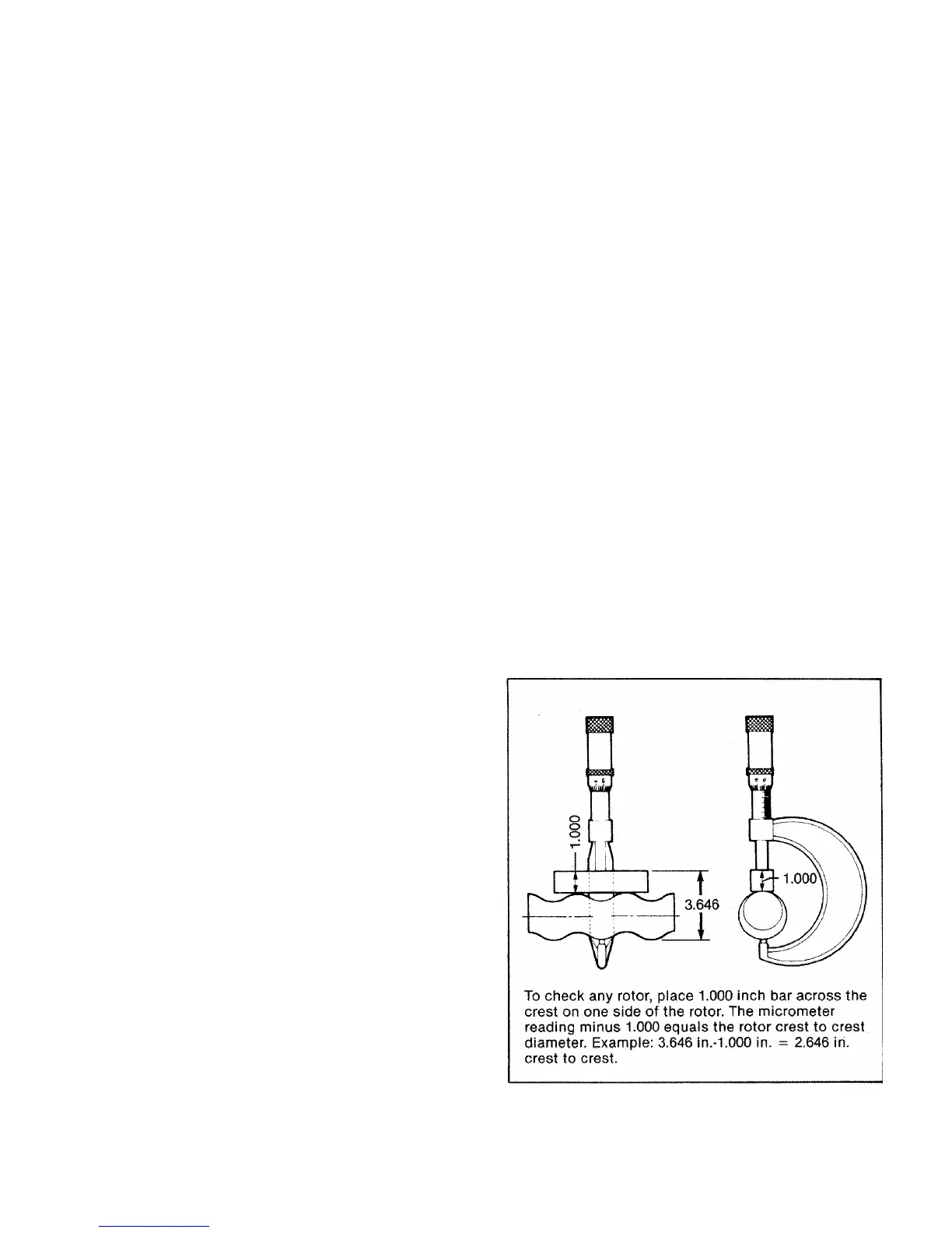
Figure 4-4. Measuring Rotor Dimension