Page 24
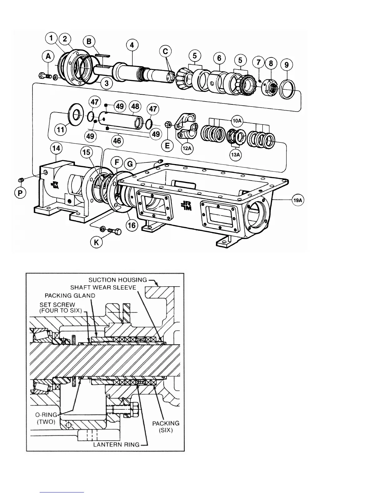
4-64. SHAFT SLEEVE ARRANGEMENT
Some pumps have a sleeve installed on the drive shaft to
receive any possible wear caused by the packing. See
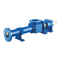
sleeve kit (46, fig. 4-11), and the cross section illustration
(fig. 4-12).
4-65. Disassembly (see fig. 4-11). After separation of bear-
ing housing (14) from suction housing (19A), and removal of
packing gland and packings, remove sleeve as follows:
1. Loosen four to six set screws (49) in sleeve (48),
and pull sleeve off shaft (4).
2. Remove two O-rings (47) from interior of sleeve.
4-66. Assembly. Assemble pump to the point where slinger
ring (11) is installed on drive shaft (4), then install sleeve kit
(46) as follows.
1. Lubricate two O-rings (47) and insert in grooves in inte-
rior of sleeve (48). Loosely install four to six set screws (49)
in sleeve, but be sure they do not protrude into interior of
sleeve.
2. Install sleeve unit (47, 48, 49) over drive shaft (4) so
that set-screw end of sleeve is in toward slinger ring (11).
3. Adjust sleeve to be flush with end of drive shaft, and
tighten the four to six set screws (49).
Figure 4-11. Shaft Sleeve Arrangement
Figure 4-12. Pump with Shaft Wear Sleeve