PAGE 28 — DCA70SSIU4F 60 HZ GENERATOR DSE8610 MKII • OPERATION MANUAL — REV. #0 (08/11/22)
OUTPUT TERMINAL PANEL CONNECTIONS
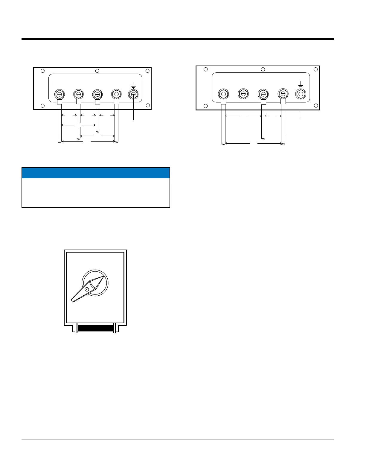
2. Connect the load wires to the UVWO terminals as
shown in Figure 18.
Figure 18. UVWO Terminal Lugs 3Ø-480V
Connections
1Ø-240/120V UVWO Terminal Output Voltages
1. Place the voltage selector switch in the 1Ø 240/120
position as shown in Figure 19.
Figure 19. Voltage Selector Switch
1Ø-240/120V Position
O
U
V
W
480V
BLACK RED
BLUE
480V
277V
480V
277V
WHITE
GREEN
277V
GROUND CONNECTION
MUST BE USED
AT ALL TIMES
NOTICE
ALWAYS make sure that the connections to the UVWO
terminals are secure and tight. The possibility of arcing
exists, that could cause a fire.
PRESS TO LOCK
3 PHASE
480/277
3 PHASE
240/139
1 PHASE
240/120
2. Connect the load wires to the UVWO terminals as
shown in Figure 20.
Figure 20. UVWO Terminal Lugs
1Ø-240/120V Connection
O
U
V
W
BLACK RED
BLUE
WHITE
GREEN
NOT USED
MUST BE USED
AT ALL TIMES
240V 120V
 Loading...