mr
.
steam
®
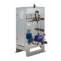
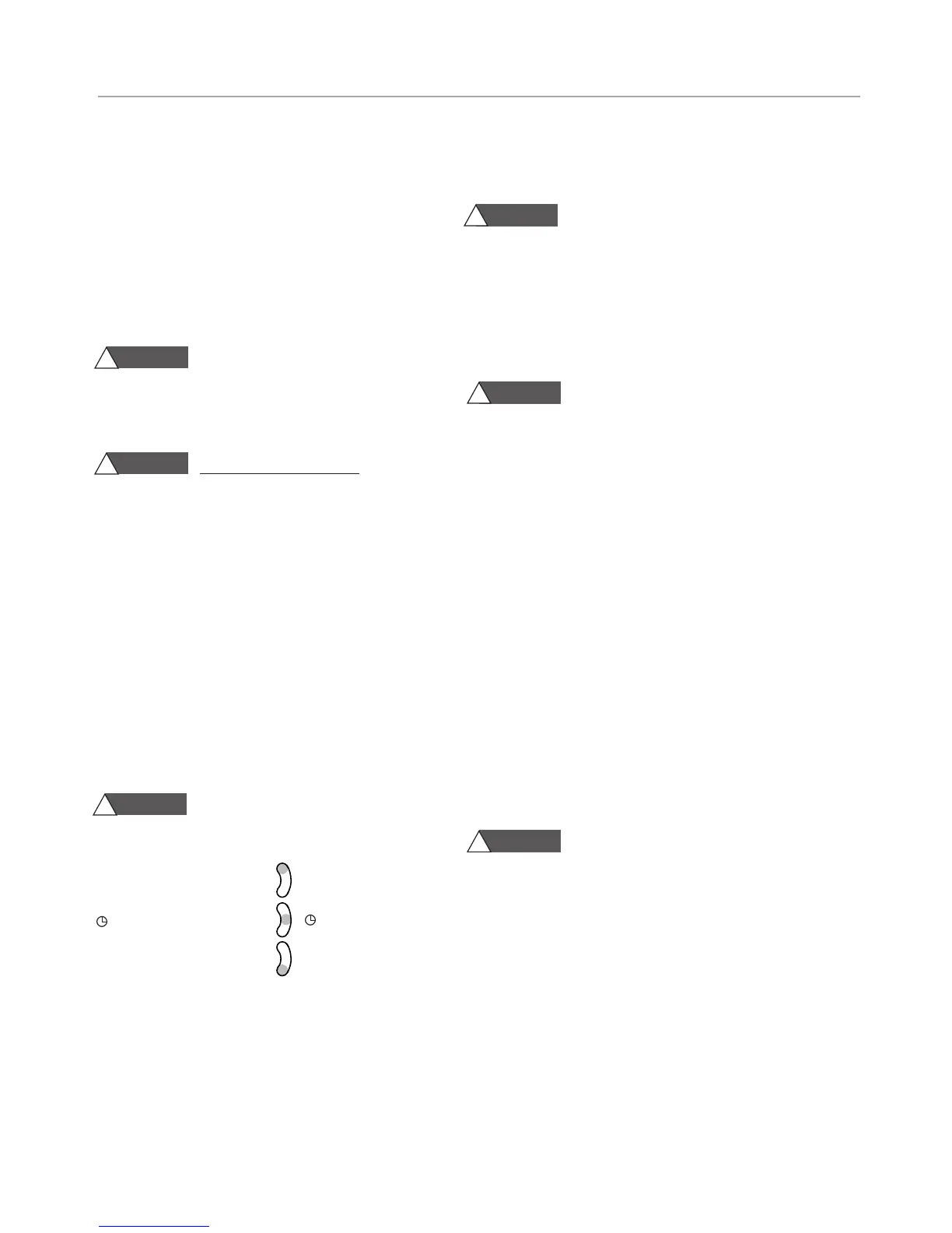
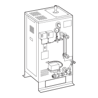
C U S E R I E S Installation, Operating & Maintenance Manual
29
TROUBLESHOOTING THE 103538C BOARD
Perform the steps below to verify proper function
Substitution of components or modification of
wiring systems voids warranty and can lead to dangerous oper-
ating conditions.
• Pulling off the purple wire from the board should cause the
water solenoid to engage and fill the unit.
• If the sightglass is full and tripped on a high water, pulling the
pink wire will release it from a high water condition and engage
the contactors(if the rest of the circuit is functioning properly).
Safety glasses and gloves should be worn at all
times when working with or examining water gauge glass and
connections.
STEP 5: Verify that you have 120V on L1 & L2 of the lower pc
board. If not you may have a problem with your upper pc board
TROUBLESHOOTING THE 90241MRT BOARD
Perform the steps below to verify proper function.
• Pull of the red wire from the 9 inch probe on the top of the
pressure vessel and physically ground it out to the pressure
vessel or the jacket. This should send voltage through the
NO (normally open) terminal on the board to engage the
contactors.
• To check a faulty test button, you can take a jumper wire and
jump across the two test button terminals. This should allow
the board to actuate correctly if the button is faulty.
• A blinking light on the pc board indicates the board is having
difficulty sensing water (either due to a dirty probe or low
conductivity in the water). Holding the reset button for 30
seconds should reset the board back to function. See next
section for maintenance schedule in locales where water
quality requires regular treatment.
Turn off all power supplies to steambath
generator and release pressure to zero (0) psig before
removing probes.
MAINTENANCE OF PROBE AND LWCO
• Inspect probe annually for scale build-up and clean if
necessary. Make certain there is no scale or build-up on
the probe or its white insulator. For cleaning instructions,
refer to page 22.
• Replace probe every 10 years. More frequent replace-
ment of the probe is required if it is used in locales
where significant water treatment is required, where
more frequent cleaning is necessary, or in applications
with high make-up water requirements.
• Replace the low water cut-off every 15 years.
IMPORTANT: For recommended feedwater quality,
refer to page 7.
IMPORTANT: Read all warnings and instructions
before performing any installation, maintenance, or
troubleshooting. These instructions are intended to
aid service personnel in isolating the issue causing the
CU Steambath generator to malfunction.
Troubleshooting does NOT substitute authorized
technical service or factory evaluation. For replace-
ment parts and warranty information, please call mr.
steam technical support at the number listed at the
bottom of this document.
Before beginning troubleshooting,
with all power disconnected at main switch, insure all
electrical and mechanical connections are tight
before energizing unit to prevent electrical problems
and mechanical leaks.
Under any circumstances, only quali-
fied service personnel should attempt the below pro-
cedures.
NOTE: Refer to wiring diagram for check points.
STEP 1: Test your main control voltage and verify you
have 120V.
STEP 2: When you have your blowdown timer set
properly and running you will have 120V at these two
points. Make sure your blowdown timer is set for a
runtime. Refer to pg 24 for full instructions on operat-
ing the blowdown timer. You must have voltage com-
ing out of the blowdown timer from the brown wire.
Have it set to run. Below are the 3 way manual over-
ride switch positions. You can set it to permanent ON
for all of the following tests.
Burn Hazard. Pressurized Steam and
Hot Water is discharged during blowdown.
3-WAY MANUAL OVERRIDE SWITCH
I = Boiler Permanent ON I
= Automatic
O
= Boiler Permanent OFF
O
STEP 3:
Make sure the on/off switch is set to the on
position. Testing here will determine if the on/off switch
is functioning. If there is no voltage then your switch is
faulty.
STEP 4: Check to see that you have 120V going to L1
& L2 of the upper PC board. If you do not have volt-
age this could mean that the room overtemp (125
degree) has tripped and cut the power to the rest of
the system.
WARNING
!
WARNING
!
WARNING
!
CAUTION
!
CAUTION
!
CAUTION
!
TROUBLESHOOTING GUIDE