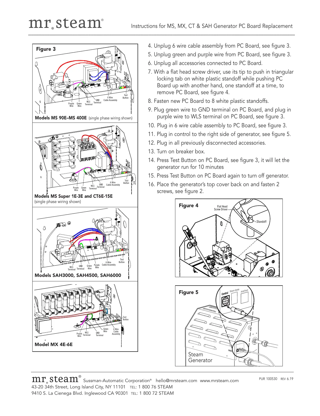
Models MS 90E–MS 400E
(single phase wiring shown)
Models MS Super 1E-3E and CT6E-15E
(single phase wiring shown)
Models SAH3000, SAH4500, SAH6000
Model MX 4E-6E
Figure 3
Figure 5
mr
.
steam
®
Sussman-Automatic Corporation
®
hello@mrsteam.com www.mrsteam.com
43-20 34th Street, Long Island City, NY 11101
TEL: 1 800 76 STEAM
9410 S. La Cienega Blvd. Inglewood CA 90301
TEL: 1 800 72 STEAM
PUR 100530 REV 6.19
4. Unplug 6 wire cable assembly from PC Board, see figure 3.
5. Unplug green and purple wire from PC Board, see figure 3.
6. Unplug all accessories connected to PC Board.
7. With a flat head screw driver, use its tip to push in triangular
locking tab on white plastic standoff while pushing PC
Board up with another hand, one standoff at a time, to
remove PC Board, see figure 4.
8. Fasten new PC Board to 8 white plastic standoffs.
9. Plug green wire to GND terminal on PC Board, and plug in
purple wire to WLS terminal on PC Board, see figure 3.
10. Plug in 6 wire cable assembly to PC Board, see figure 3.
11. Plug in control to the right side of generator, see figure 5.
12. Plug in all previously disconnected accessories.
13. Turn on breaker box.
14. Press Test Button on PC Board, see figure 3, it will let the
generator run for 10 minutes
15.
Press Test Button on PC Board again to turn off generator.
16. Place the generator’s top cover back on and fasten 2
screws, see figure 2.