DESCRIPTION MSA
6 BD 96 SL
GB
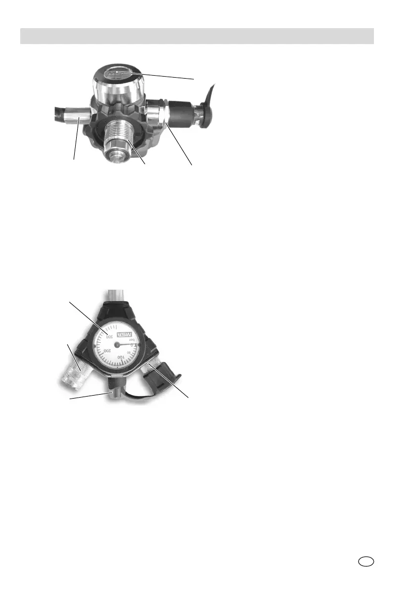
Fig. 2 Pressure reducer
1 Multi-channel line connection
2 Compressed air cylinder connection
3 Quick-Fill coupling (not for standard model)
4 Lead seal
The pressure reducer (see Fig. 2) is mounted in the lower area of the carrying
plate. On the pressure reducer, there is a safety valve and the multi-channel line
for connecting the combo pressure gauge. The pressure reducer reduces the
cylinder pressure to approx. 7 bar and the safety valve activates on non-permitted
pressure rise to prevent damage insuring the continued supply of breathable air.
Fig. 3 Combo-pressure gauge
1 Pressure gauge
2 Lung governed demand valve connection
3 Warning device (signal whistle)
4 Second connection
The combo pressure gauge (see Fig. 3) is connected at the end of the multi-
channel line. It consists of the pressure gauge (1) itself, the coupling for the lung
governed demand valve (2) as well as an acoustic warning device (3) (signal
whistle). It triggers a continuous warning signal when the cylinder pressure drops
below 55±5 bar. The second connection (4) connects a second lung governed
demand valve (e.g. backup set).
3
1
3
1
4
4