USING THE AIR MASK
feature that records information about the air mask while
t
he FireHawk M7 Control Module is turned on. This data
log memory can be accessed using the FireHawk M7
C
ontrol Module Reader/ID Tag Writer interface.
• The FireHawk M7 Control Module contains an internal
real time clock. This clock can be reset using the
FireHawk M7 Control Module Reader/ID Tag Writer
interface. By default, the internal clock is set to
E
astern Standard Time.
USING THE FIREHAWK M7 CONTROL MODULE
Note: Refer to Chart 2 for the various audible and visual
indicators.
FIREHAWK M7 CONTROL MODULE THERMAL ALARM
The FireHawk M7 Control Module can monitor tempera-
ture conditions if the thermal alarm option is activated. If
the user is exposed to more than a pre-set limit of
time/temperature, the thermometer icon on the FireHawk
M7 Control Module display will flash and the FireHawk M7
Power Module will sound a tone every 3 seconds.
Although this thermal alarm provides an indication
that the time-temperature curve is exceeded, the
curve may not represent the threshold to injury due to
variations in individuals and the protective clothing
worn. Use this alarm as a reference only to increasing
time-temperature. Do not use as a substitute for stan-
dard operating procedures regarding escape from
time-temperature extremes. Failure to do so can result
in serious personal injury or death.
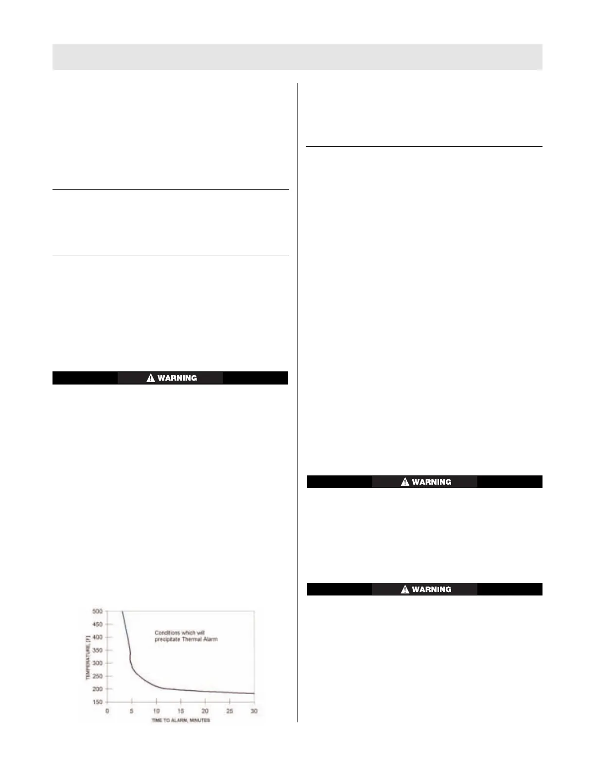
Chart 3 shows the FireHawk M7 Control Module thermal
alarm activation curve. The time/temperature limits corre-
spond to this graph. The thermal alarm sounds if the pre-
set limit exceeds the curve displayed on the graph. The
alarm will self-cancel depending on the severity of condi-
tions. This may occur even though the temperature is
above the thermal curve.
Chart 3: FireHawk M7 Control Module Thermal Alarm
Activation Curve
Note: This chart was generated from data obtained in a
l
aboratory setting and is for reference only. Conditions are
highly variable in an actual use scenario. Users of the
F
ireHawk M7 Control Module with the thermal alarm option
should develop procedures for the use of this feature.
D
URING USE
Note: Refer to Chart 2 for the various audible and visual
indicators for the FireHawk M7 Control Module and
FireHawk M7 Power Module.
Pressure Display
1. Periodically check the pressure indicated on the
FireHawk M7 Control Module display. It will display
either remaining cylinder pressure (default) or calculat-
ed remaining service time.
2. When the pressure reaches 25% of the rated service
pressure, the alarm button on the FireHawk M7
Control Module will flash red and the FireHawk M7
Responder HUD will display one flashing red LED.
3. When the pressure reaches approximately 25% of the
rated service pressure, return to fresh air.
Changing the FireHawk M7 Control Module Display
Mode
1. Press the top mode button (green) once. This will
momentarily refresh FireHawk M7 Responder HUD
display as well as light the FireHawk M7 Control
Module display.
2. While the FireHawk M7 Control Module display is still
lit, press the top mode button (green) again. This will
toggle the display from remaining cylinder pressure to
calculated remaining service time.
The FireHawk M7 Control Module has the ability to
display calculated remaining service time counting
down to 0 psi (default) or 25% of the rated service
pressure. The user must determine which option has
been selected for the FireHawk M7 Control Module in
service. Failure to follow this warning can result in
serious personal injury or death.
Actual time remaining may be less than the calculated
time displayed. Increases in breathing rate may reduce
remaining time more than expected. Use time indica-
tor as general guide only. The time displayed is based
on the continuation of the average breathing rate over
the last three minutes. Increases in the breathing rate
after checking the displayed time may result in less
remaining time than anticipated. Failure to follow this
warning can result in serious personal injury or death.
27
TAL 803 (L) Rev. 1 - 10086011
 Loading...