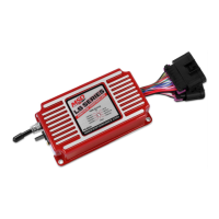
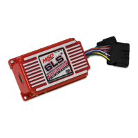
2 INSTALLATION INSTRUCTIONS
MSD • WWW.MSDPERFORMANCE.COM • (915) 855-7123 • FAX (915) 857-3344
PINK Step Retard. When 12-volts are supplied, the Step Retard is activated.
BLUE Two-Step. When 12-volts are supplied, the Launch Rev Limiter RPM value is active.
GRAY Tach. Provides a 12-volt square wave signal.
RED Battery Positive. From relay or dedicated fused 30A switch.
BLACK Battery Negative
CAM/CRANK SENSOR - 10 PIN
ORANGE/YELLOW Pin-1 Crank
BROWN/WHITE Pin-2 Cam
ORANGE Pin-3 5-volt supply
PINK Pin-4 12-volt supply
BROWN Pin-6 Sensor Ground
ENGINE COOLANT TEMP SENSOR (ECT)
BLACK Pin-1 Sensor Ground
YELLOW Pin-2 Engine Coolant Signal
COIL CONNECTOR - EVEN CYLINDERS
BLACK Pin-A Chassis Ground
RED/GREEN Pin-B Coil 2
BROWN/GREEN Pin-C Coil 4
Pin-D Not Used
BROWN Pin-E Sensor Ground
WHITE/BLUE Pin-F Coil 6
VIOLET/BLUE Pin-G Coil 8
PINK Pin-H 12-volt supply
COIL CONNECTOR - ODD CYLINDERS
BLACK Pin-A Chassis Ground
RED Pin-B Coil 7
GREEN Pin-C Coil 5
Pin-D Not Used
BROWN Pin-E Sensor Ground
BLUE Pin-F Coil 3
VIOLET Pin-G Coil 1
PINK Pin-H 12-volt supply
WIRING FEATURES