EasyManua.ls Logo

MSD 6421 User Manual

MSD 6421
28 pages
To Next Page IconTo Next Page
Page #1 background imageLoading...
Page #1 background image
MSD •  WWW.MSDPERFORMANCE.COM •  (915)  855-7123  •  FAX  (915)  857-3344
Parts Included:
1 - MSD Ignition 1 - Screwdriver 4 - Vibration Mounts
1 - Harness, PN 8860 1 - Parts Bag, ASY 28928
WARNING: During installation, disconnect the battery cables. When disconnecting the battery always
remove the Negative cable first and install it last.
Note: Solid Core spark plug wires cannot be used with an MSD Ignition.
Note: Do not use digital or dial back timing lights.
LED INDICATOR
There is an LED that monitors the status of the Ignition. The LED monitors the trigger signals and will
flash to warn if the supply voltage drops below 9 volts while under 3,000 rpm.
OPERATION AND FEATURES
DIGITAL OPERATION
The MSD 6AL-2 uses a high speed RISC microcontroller to control the ignition's output while constantly
analyzing the various inputs such as supply voltage, trigger signals and rpm. The high speed con-
troller can make extremely quick compensations to the output voltage, multiple spark series, timing
and rpm limits while maintaining accurate timing signals to within 1° and 1% of the rpm limits. The
circuits and controller of the 6AL-2 have been thoroughly filtered to create protection against Electro
Magnetic Interference (EMI).
CAPACITIVE DISCHARGE
The MSD 6AL-2 features a capacitive discharge ignition design. The majority of stock ignition
systems are inductive ignitions. In an inductive ignition, the coil must store and step up the voltage
to maximum strength in between each firing. At higher rpm, since there is less time to charge the coil
to full capacity, the voltage falls short of reaching maximum energy which results in a loss of power
or top end miss.
The MSD Ignition features a capacitor which is quickly charged with 520 - 535 volts and stores it until
the ignition is triggered. With the CD design, the voltage sent to the coil is always at full power even
at high rpm.
MULTIPLE SPARKS
The MSD produces full power multiple sparks for each firing of a plug. The number of multiple sparks
that occur decreases as rpm increases, however the spark series always lasts for 20° of crankshaft
rotation. Above 3,000 rpm there is simply not enough “time” to fire the spark plug more than once,
so there is only one powerful spark.
PROTECTION
The MSD 6AL-2 has a built in reverse polarity protection circuit. This will protect the ignition in the
event of wrong connections. It will also shut off for protection from a surge in power. The ignition will
still operate once the surge or polarity is corrected.
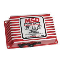
MSD 6AL-2 Ignition Control
PN 6421
ONLINE PRODUCT REGISTRATION: Register your MSD product online. Registering your product
will help if there is ever a warranty issue with your product and helps the MSD R&D team create
new products that you ask for! Go to www.msdperformance.com/registration.

Table of Contents

Question and Answer IconNeed help?

Do you have a question about the MSD 6421 and is the answer not in the manual?

MSD 6421 Specifications

General IconGeneral
BrandMSD
Model6421
CategoryControl Unit
LanguageEnglish

Summary

Operation and Features

Rev Limiter Functionality

Soft Touch Rev Control

Features a Soft Touch Rev Control with two adjustable rpm limits for smooth operation.

Mounting Instructions

Wiring Harness Overview

Power and Ground Connections

Heavy Red to battery positive, Heavy Black to battery negative or engine ground.

Control and Coil Connections

Red for ignition switch, Orange to coil positive, Black to coil negative.

Trigger Signal Options

Options include Points (White), Magnetic Pickup (Green/Violet), Hall-effect (White/Blue).

Accessory Connections

Blue wire for 2-Step Rev Control, Gray wire for Tach Output.

Grounding Procedures

Wire Routing for Interference Reduction

Programming the Ignition

Cylinder Count Selection

Select the engine cylinder count using the rotary switch for proper operation.

Rev Limiter Settings

Adjust Max Limit and Two Step Limit in 100 rpm increments using side rotary switches.

Max RPM Limit Adjustment

Sets the overrev rpm limit; adjustable from 2,000 to 11,900 rpm.

Two-Step RPM Limit

Pre-Start Checklist

Troubleshooting Guide

No-Run Issues on Foreign Vehicles

Inoperative Tachometers

Engine Run-On Correction

Misses and Intermittent Problems

Checking for Spark

Spark Test with White/Blue Wire Trigger

Tap White wire to ground; spark should jump from coil wire to ground.

Spark Test with Magnetic Pickup Trigger

Short Green/Violet wires together; spark should jump from coil wire to ground.

Troubleshooting No Spark Condition

Inspect wiring, substitute coil, check 12V on Red wire, or consider MSD repair.

MSD System Wiring Diagrams

Wiring: Points/Amplifier Ignition

Diagram for connecting MSD 6AL-2 to points or amplifier style ignitions.

Wiring: Hall-Effect Trigger Distributor

Diagram for connecting MSD 6AL-2 to Hall-Effect trigger distributors.

Wiring: MSD Timing Control (Points/Amplifier)

Diagram for connecting MSD 6AL-2 with a separate MSD Timing Control.

Wiring: MSD Distributor/Crank Trigger

Diagram for connecting MSD 6AL-2 to MSD distributors or crank triggers.

Wiring: MSD Distributor PN 8360

Diagram for connecting MSD 6AL-2 to MSD Distributor PN 8360.

GM Ignition Wiring Diagrams

GM & MSD System Wiring Diagrams

GM HEI & Ford Ignition Wiring Diagrams

Ford Ignition Wiring Diagrams

Ford & Chrysler Ignition Wiring Diagrams

Chrysler & Honda Ignition Wiring Diagrams

Honda Ignition Wiring Diagrams

Import & Aftermarket Wiring

Aftermarket Component Wiring Diagrams

Atomic EFI System Wiring

Service and Warranty Information

Related product manuals