2 INSTALLATION INSTRUCTIONS
MSD • WWW.MSDPERFORMANCE.COM • (915) 855-7123 • FAX (915) 857-3344
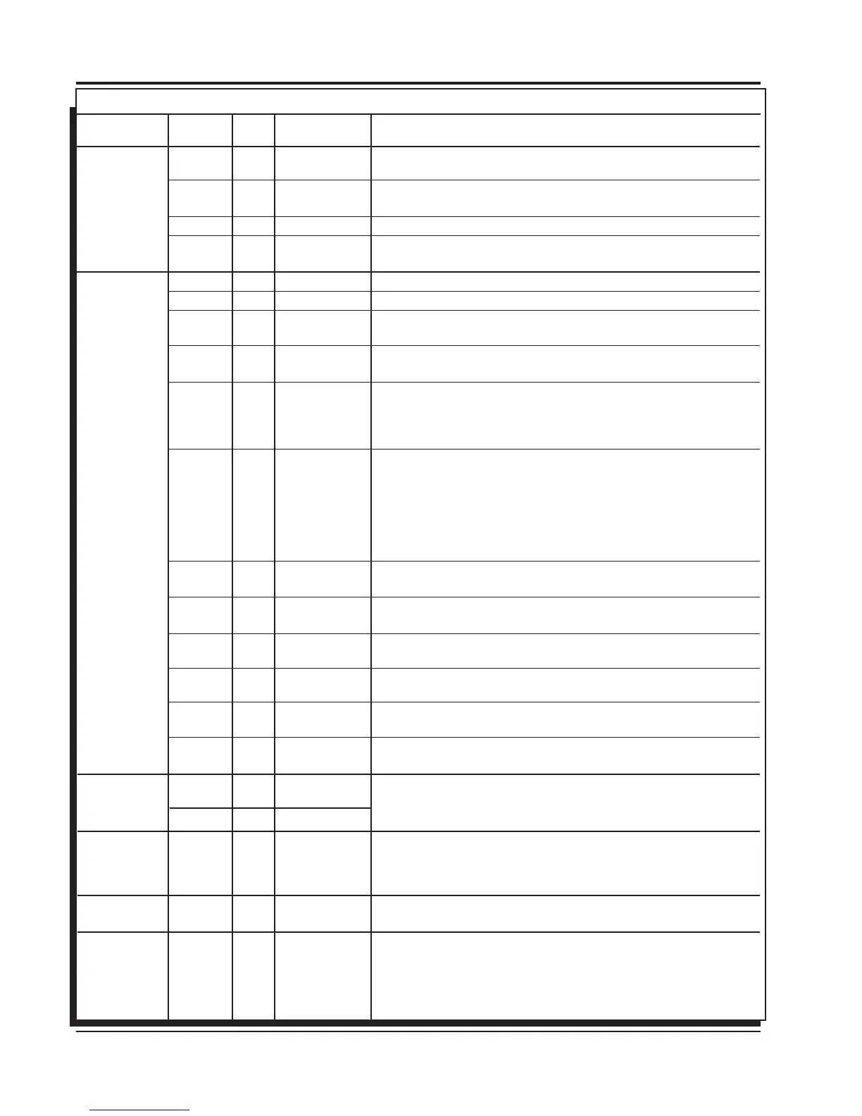
4-Pin
Connector
(to PN 7720
or Power
Cable if not
used with
PN 7720)
LOOSE
WIRES
2-Pin
Connector
(Legacy)
3-Pin
Connector
Racepak
Assembly
6-Pin
Connector
(to Hub/
Modules)
Color PIN Function Description
BLACK 16 GROUND Ignition supply Ground wire. Connect to battery negative (-) terminal
or engine block.
ORANGE 17 BATT POWER Battery supply wire. Connects to battery positive (+) terminal or battery
junction. Note: Do not connect to the alternator.
YEL/WHT 33 TRIGGER OUT Trigger output for electronic ignition amplifiers.
RED 34 POWER OUT On/Off switch wiring. This wire supplies switched 12V power to the
7720.
RED 15 IGN 12V switched (Ignition)
GRAY 18 TACH Tach output. This wire will provide a 12 volt square wave tach signal.
WHITE 32 POINTS IN Trigger input from electronic ignition amplifiers, an ECU’s trigger or
points.
YELLOW 1 SHIFT LIGHT Shift Light output wire. It can handle up to 3 amps continuous to ground
when enabled.
LT BLUE 4 BURN OUT Burnout Rev Limit. When 12 volts are applied the Burnout Rev Limit is
active. This disables the Slew Rate rev limits and overrides other rev limits.
It is recommended to have this wire switched from an outside source, such
as the crew chief before the burnout and while staging the car.
DK BLUE 21 LAUNCH This wire activates the Launch Rev Limit and is the main reset wire for
several features of the Ignition. When 12 volts are applied to this wire it
will activate the Launch Rev Limit. It also resets the shift light, the gear
indicator to first gear, the Launch Retard curve and select Gear 1 curve.
When 12 volts is removed, the Launch Time begins as does the Gear 1
curve. When 12 volts are applied the Slew Rate Rev limit will be disabled
as well as the Time-Based Rev Limit curve.
PINK 22 STEP 1 Step 1 retard enabled with +12 volt input AND above Step 1 Rpm value
OR Gear 2 Select.
VIOLET 5 STEP 2 Step 2 retard enabled with +12 volt input AND above Step 2 Rpm value
OR Gear 3 Select.
TAN 23 STEP3 Step 3 retard enabled with +12 volt input AND above Step 3 Rpm value
OR Gear 4 Select.
LT GREEN 6 STEP4 Step 4 retard enabled with +12 volt input AND above Step 4 Rpm value
OR Gear 5 Select.
GREEN 10 STEP5 Step 5 retard enabled with +12 volt input AND above Step 5 Rpm value
OR spool rev limiter.
BRN/WHT 19 RPM SW RPM/Time switch output wire. It can switch up to 3 amps continuous
to ground when enabled.
YELLOW 7 RELAY LO Network Ignition Mode: Cam sync output to Racepak systems for
individual cylinder timing.
YELLOW 24 RELAY HI Legacy Ignition Mode: Rev limiter output to legacy ignition..
GREEN 8 MAG- This is a magnetic pickup, 2-pin connector. Plugs into an MSD
VIOLET 9 MAG+ Distributor or Crank Trigger pickup. Violet is positive, Green is negative.
BROWN 25 SHIELD Note: When this connector is used, the white POINTS IN wire is not
connected. Brown connects to ground.
WHITE 11 VNET HI Communicates data acquisition information with RacePak system.
BLACK VNET LO Only used to plug into VNet.
RED 13 MSD CAN HI Supplies 12V switched power to add on module units. Also communicates
between modules and Power Grid System Controller. This connector
is only used with modules added onto the system. This is for the MSD
CAN-Bus accessories. It is only used when adding Power Grid Modules
to the system. The Hub Connector, PN 7769, is required.
BROWN 27 SHIELD
RED 29 POWER OUT
BLACK 30 MSD CAN LO
BLACK 31 MSD CAN GND
Leading
Group
Wire
or
WIRING FEATURES
 Loading...