INSTALLATION INSTRUCTIONS 3
MSD • WWW.MSDPERFORMANCE.COM • (915) 855-7123 • FAX (915) 857-3344
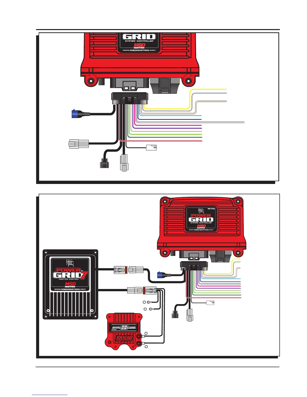
RED - 12V SW OUT
BLACK - BATTERY (-)
ORANGE - BATTERY 12V
WHITE - POINTS OUT
MSD
CAN
MAG PICKUP
CONNECTOR
LEGACY IGNITION
SWITCHED IGNITION 12V
GREEN - STEP 5
LT. GREEN - STEP 4
TAN - STEP 3
VIOLET - STEP 2
PINK - STEP 1
BLUE - LAUNCH
LT. BLUE - BURN OUT
BRN/WHITE - RPM/TIME SWITCH
WHITE - POINTS IN
GRAY - TACH
YELLOW - SHIFT LIGHT
V-NET
CABLE
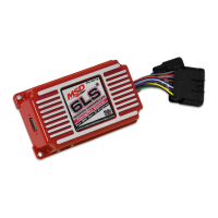
Figure 1 Wires of the Power Grid System Controller.
Figure 2 Wiring the Power Grid.
NOTE: SEE PAGES 10-12 FOR SCHEMATICS
SHOWING INSTALLATION TO OTHER
MSD IGNITION CONTROLS.
RED - 12V SW OUT
BLACK - BATTERY (-)
ORANGE - BATTERY 12V
WHITE - POINTS OUT
MSD
CAN
MAG PICKUP
CONNECTOR
LEGACY IGNITION
SWITCHED IGNITION 12V
GREEN - STEP 5
LT. GREEN - STEP 4
TAN - STEP 3
VIOLET - STEP 2
PINK - STEP 1
BLUE - LAUNCH
LT. BLUE - BURN OUT
BRN/WHITE - RPM/TIME SWITCH
WHITE - POINTS IN
GRAY - TACH
YELLOW - SHIFT LIGHT
ORANGE
BLACK
+
+
-
-
TO BATTERY POSITIVE
TO BATTERY NEGATIVE
HEAVY RED
HEAVY BLACK
V-NET
CABLE
VNET Connector
4-Pin Deutsch connector
3-Pin Deutsch connector
4-Pin Deutsch connector Female
VN7730 Harness
Connectors
Mating Pieces If any
3-Pin Deutsch connector Female