INSTALLATION INSTRUCTIONS 5
MSD • WWW.MSDPERFORMANCE.COM • (915) 855-7123 • FAX (915) 857-3344
PROGRAMMABLE FEATURES AND SETTINGS:
GENERAL
These are the most basic settings of the system. They will need to be set the first time the system is installed
in a vehicle.
Number of Cylinders: This tells the system the number of cylinders. Must be selected correctly for proper
timing and rev limiting.
Maximum Timing Reference: This is the advance that is set with a locked distributor or crank trigger. The
system controller will use this as its base for all timing marks and can never advance past the pre-set
point. It is critical that this advance is set properly.
Note: When using EFI the max timing reference and the main timing must be the same number.
Number of Gears: This tells the system the number of gears used in the transmission. This information can
be used a variety of ways depending on the functions and modules used in the system.
Ignition Type: Found under General Settings, this option allows a user to select between using the Power
Grid Ignition, PN 7720, or one of the MSD legacy ignitions.
DIAGNOSTIC LED INDICATOR
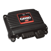
The LED is located on the far right side of the Power Grid Controller, next to the USB/SD Card cover. This
LED allows the user to quickly determine if; all systems are normal, data is being recorded or if there are
any active Alerts.
OFF – Unit is turned off
ORANGE for 1 Second – Power ON LED test
ORANGE for 10 Seconds – ARC Module (PN 7761) has been connected (*see notes below)
ORANGE - blinking – Data recording in process
GREEN - blinking – Input (crank pickup or Points wire) triggered; below 500 rpm, no active Alerts
RED - blinking – Input (crank pickup or Points wire) triggered; below 500 rpm, 1 or more active
Alerts
GREEN - solid – Running; above 500 rpm, no active Alerts
RED - solid – Running; above 500 rpm, 1 or more active Alertys
*NOTE: Many racing organizations (NHRA, IHRA, etc.) use an MSD Power Grid test tool that can check for
the following settings:
1. ARC Module - indicates if an ARC module (PN 7761) has been connected (Holds connection indicator
for the next 60 minutes of engine run time after the ARC codule has been disconnected)
2. Safety Limiter - the RPM that the engine will be limited to if it exceeds the Safety Run Time limit.
3. Safety Run Time - the run time, in seconds, after the Launch input (Blue wire) has been released. Activates
the Safety Limiter when timer reaches 0 seconds.
4. Part Numbers - lists the part numbers of any MSD compatible module connected to the Power Grid system.
5. Over Boost - Boost pressure ignition cut off value of the MSD Boost Controller (PN 7763). If connected.
CAMSHAFT SYNCHRONIZATION
This is used only in applications where the individual cylinder timing is going to be used. The fiber optic
connector communicates when the #1 cylinder fires. With this information, the controller knows which cyl-
inder is being fired allowing for the individual cylinder timing capabilities. Only the MSD Fiber Optic Induc-
tive Pickup Kit, PN 7555 will work for this system. Cam-sync’s cylinder #1 identification is also used in the
data acquisition recordings.

 Loading...