7
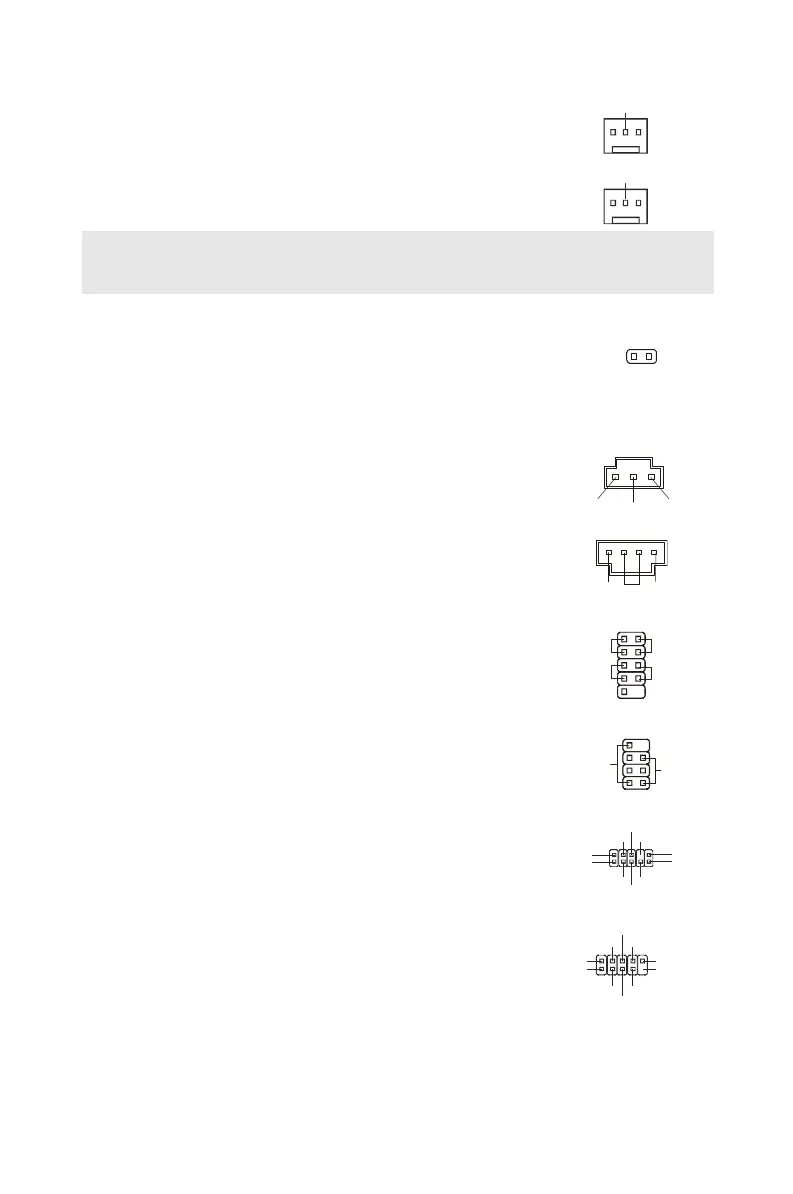
The fan power connectors support system cooling fan with
+12V. When connecting the wire to the connectors, always note
that the red wire is the positive and should be connected to the
+12V; the black wire is Ground and should be connected to
GND. If the mainboard has a System Hardware Monitor chipset
on-board, you must use a specially designed fan with speed
sensor to take advantage of the CPU fan control.
GND
GND
Important:
Please refer to the recommended CPU fans at processor’s official website or consult the
vendors for proper CPU cooling fan.
Chassis Intrusion Connector: JCI1
This connector connects to the chassis intrusion switch cable. If
the chassis is opened, the chassis intrusion mechanism will be
activated. The system will record this status and show a
warning message on the screen. To clear the warning, you
must enter the BIOS utility and clear the record.
CINTRU
S/PDIF-Out Connector: JSPD1
This connector is used to connect S/PDIF (Sony & Philips
Digital Interconnect Format) interface for digital audio
transmission.
VCC
CD-In Connector: CD_IN1
This connector is provided for external audio input.
L R
Front Panel Connectors: JFP1~2
These connectors are for electrical connection to the front
panel switches and LEDs. The JFP1 is compliant with Intel
®
Front Panel I/O Connectivity Design Guide.
JFP1
HDD
LED
Reset
Switch
LED
JFP2
LED
Speaker
Front Panel Audio Connector: JAUD1
This connector allows you to connect the front panel audio and
is compliant with Intel
®
Front Panel I/O Connectivity Design
Guide.
(2)GND
VCC5
NC
(1)MIC_L
Line-out_R
Line_JD(10)
(2)GND
MIC_R
Front to Sense
Front USB Connector: JUSB1~2
This connector, compliant with Intel
®
I/O Connectivity Design
Guide, is ideal for connecting high-speed USB interface
peripherals such as USB HDD, digital cameras, MP3 players,
printers, modems and the like.
(2)VCC
USB1-
GND
(1)VCC
USB0-
GND
PDF created with pdfFactory Pro trial version www.pdffactory.com
 Loading...