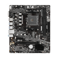
34
Overview of Components
1
212
11
1 SPI Power 2 SPI Chip Select
3
Master In Slave Out (SPI Data)
4
Master In Slave In (SPI Data)
5 Reserved 6 SPI Clock
7 Ground 8 SPI Reset
9 Reserved 10 No Pin
11 Reserved 12 Interrupt Request
JTPM1: TPM Module Connector
This connector is for TPM (Trusted Platform Module). Please refer to the TPM security
platform manual for more details and usages.
BAT1
BAT1
CPU_FAN1, SYS_FAN1: Fan Connectors
Fan connectors can be classified as PWM (Pulse Width Modulation) Mode or DC Mode.
PWM Mode fan connectors provide constant 12V output and adjust fan speed with
speed control signal. DC Mode fan connectors control fan speed by changing voltage.
The auto mode fan connectors can automatically detect PWM and DC mode. However,
you can follow the instruction below to adjust the fan connector to PWM or DC Mode
manually.
CPU_FAN1
SYS_FAN1
Connector
Default fan
mode
Max.
current
Max.
power
CPU_FAN1 Auto mode 2A 24W
SYS_FAN1 DC mode 1A 12W
Switching fan mode and adjusting fan speed
You can switch between PWM mode and DC mode and adjust fan speed in BIOS >
HARDWARE MONITOR.
 Loading...

