EasyManua.ls Logo

MSI H110M PRO-VD User Manual

MSI H110M PRO-VD
148 pages
To Next Page IconTo Next Page
Page #1 background imageLoading...
Page #1 background image
1
󴻡󲦃
Contents
Contents
 2
 3
 6
LAN Port LED Status Table ................................................................................6
 7
CPU Socket ........................................................................................................8
DIMM Slots .........................................................................................................9
PCI_E1~3: PCIe Expansion Slots .......................................................................9
SATA1~4: SATA 6Gb/s Connectors .................................................................10
JFP1, JFP2: Front Panel Connectors ...............................................................10
JPWR1~2: Power Connectors ..........................................................................11
JUSB1: USB 2.0 Connector ..............................................................................11
JUSB3: USB 3.1 Gen1 Connector ....................................................................12
JAUD1: Front Audio Connector ........................................................................12
JCOM1: Serial Port Connector .........................................................................12
CPUFAN1, SYSFAN1: Fan Connectors ...........................................................13
JTPM1: TPM Module Connector.......................................................................14
JCI1: Chassis Intrusion Connector ...................................................................14
JBAT1: Clear CMOS (Reset BIOS) Jumper .....................................................15
EZ Debug LED: Debug LED indicators .............................................................15
 
Entering BIOS Setup.........................................................................................16
Resetting BIOS .................................................................................................17
Updating BIOS ..................................................................................................17
 
Installing Windows
®
7/ 8.1/ 10 ...........................................................................18
Installing Drivers ...............................................................................................18
Installing Utilities ...............................................................................................18
Thank you for purchasing the MSI
®
motherboard 
. This User Guide
gives information about board layout, component overview
and BIOS setup.

Table of Contents

Question and Answer IconNeed help?

Do you have a question about the MSI H110M PRO-VD and is the answer not in the manual?

MSI H110M PRO-VD Specifications

General IconGeneral
Form FactorMicro ATX
ChipsetIntel H110
CPU SocketLGA 1151
Memory Slots2 x DIMM
Maximum Memory32 GB
Expansion Slots1 x PCIe 3.0 x16, 2 x PCIe 2.0 x1
Storage Interface4 x SATA 6Gb/s
Memory Speed2133 MHz
USB Ports6 x USB 2.0
AudioRealtek ALC887
LANRealtek RTL8111H Gigabit LAN
Video Outputs1 x VGA

Summary

Safety Information

Specifications

CPU and Chipset Details

Details on CPU support and the motherboard chipset.

Memory and Expansion Slots

Information on DDR4 memory slots and PCIe expansion slots.

Connectivity and Audio Specs

Specifications for onboard graphics, storage, USB, audio, and LAN.

Rear I/O Panel

H110M PRO-VH Rear Panel Layout

Diagram and description of the rear I/O ports for H110M PRO-VH.

H110M PRO-VD/H110M PRO-D Rear Panel Layout

Diagram and description of the rear I/O ports for H110M PRO-VD/H110M PRO-D.

LAN Port LED Status Table

Table explaining the status and speed indicators for the LAN port.

Overview of Components

CPU Socket and DIMM Slots

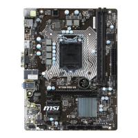
Identification and location of the CPU socket and DIMM slots.

Expansion Slots and SATA Connectors

Location of PCIe expansion slots and SATA 6Gb/s connectors.

Front Panel and Power Connectors

Identification of front panel connectors (JFP1, JFP2) and power connectors (JPWR1-2).

Internal Connectors Overview

Location of USB, audio, serial, fan, TPM, and chassis intrusion connectors.

Clear CMOS Jumper and EZ Debug LEDs

Location of the JBAT1 jumper and EZ Debug LED indicators.

CPU Socket Installation

Important CPU Socket Handling

Crucial steps and precautions for installing a CPU and handling the socket.

DIMM Slots and PCIe Expansion Slots

DIMM Slot Installation Guide

Instructions on how to install memory modules into the DIMM slots.

PCIe Expansion Slot Usage

Information on using PCIe expansion slots.

Important PCIe Expansion Slot Handling

Precautions for adding or removing expansion cards.

SATA and Front Panel Connectors

SATA 6Gb/s Connector Details

Information on SATA connectors and cable handling.

Front Panel Connectors (JFP1, JFP2)

Pinout and connection details for JFP1 and JFP2 front panel connectors.

Power and USB 2.0 Connectors

JPWR1~2 Power Connector Details

Pinout information for ATX power connectors JPWR1 and JPWR2.

JUSB1 USB 2.0 Connector Pinout

Pinout details for connecting USB 2.0 devices on the front panel.

USB 3.1 Gen1, Audio, and Serial Connectors

JUSB3 USB 3.1 Gen1 Connector Pinout

Pinout details for connecting USB 3.1 Gen1 devices on the front panel.

JAUD1 Front Audio Connector Pinout

Pinout details for connecting front panel audio jacks.

JCOM1 Serial Port Connector Pinout

Pinout details for the optional serial port connector.

Fan Connectors and Speed Control

CPUFAN1, SYSFAN1 Connector Types

Explanation of PWM and Voltage Mode fan connectors.

Fan Speed Control Methods

Ways to manage fan speed via BIOS or COMMAND CENTER.

TPM and Chassis Intrusion Connectors

JTPM1 TPM Module Connector Pinout

Pinout details for the Trusted Platform Module connector.

JCI1 Chassis Intrusion Connector and Usage

Connecting and using the chassis intrusion detector and warning reset.

Clear CMOS Jumper and EZ Debug LEDs

JBAT1 Clear CMOS (Reset BIOS) Jumper

Instructions for resetting the BIOS using the JBAT1 jumper.

EZ Debug LED Indicators

Explanation of the EZ Debug LED indicators for system status.

BIOS Setup

Entering BIOS Setup Methods

Methods to access the BIOS setup utility.

BIOS Function Key Guide

Reference for function keys used within the BIOS setup.

BIOS Reset and Update

Resetting BIOS to Default Values

Procedures for restoring BIOS settings to their default configurations.

Updating BIOS with M-FLASH

Steps for updating the BIOS using the M-FLASH utility.

Updating BIOS with Live Update 6

Steps for updating the BIOS using the Live Update 6 software.

Software Description

Installing Windows 7/8.1/10

Guide for installing Windows operating systems on the motherboard.

Installing Drivers

Instructions for installing necessary hardware drivers.

Installing Utilities

Guide for installing motherboard utility software.

Related product manuals