35
Overview of Components
1
2 26
25
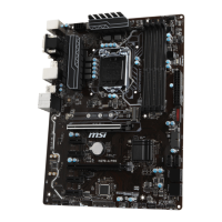
1 RSTB# 2 AFD# 3 PRND0
4 ERR# 5 PRND1 6 PINIT#
7 PRND2 8 LPT_SLIN# 9 PRND3
10 Ground 11 PRND4 12 Ground
13 PRND5 14 Ground 15 PRND6
16 Ground 17 PRND7 18 Ground
19 ACK# 20 Ground 21 BUSY
22 Ground 23 PE 24 Ground
25 SLCT 26 No Pin
JLPT1: Parallel Port Connector
This connector allows you to connect the optional parallel port with bracket.
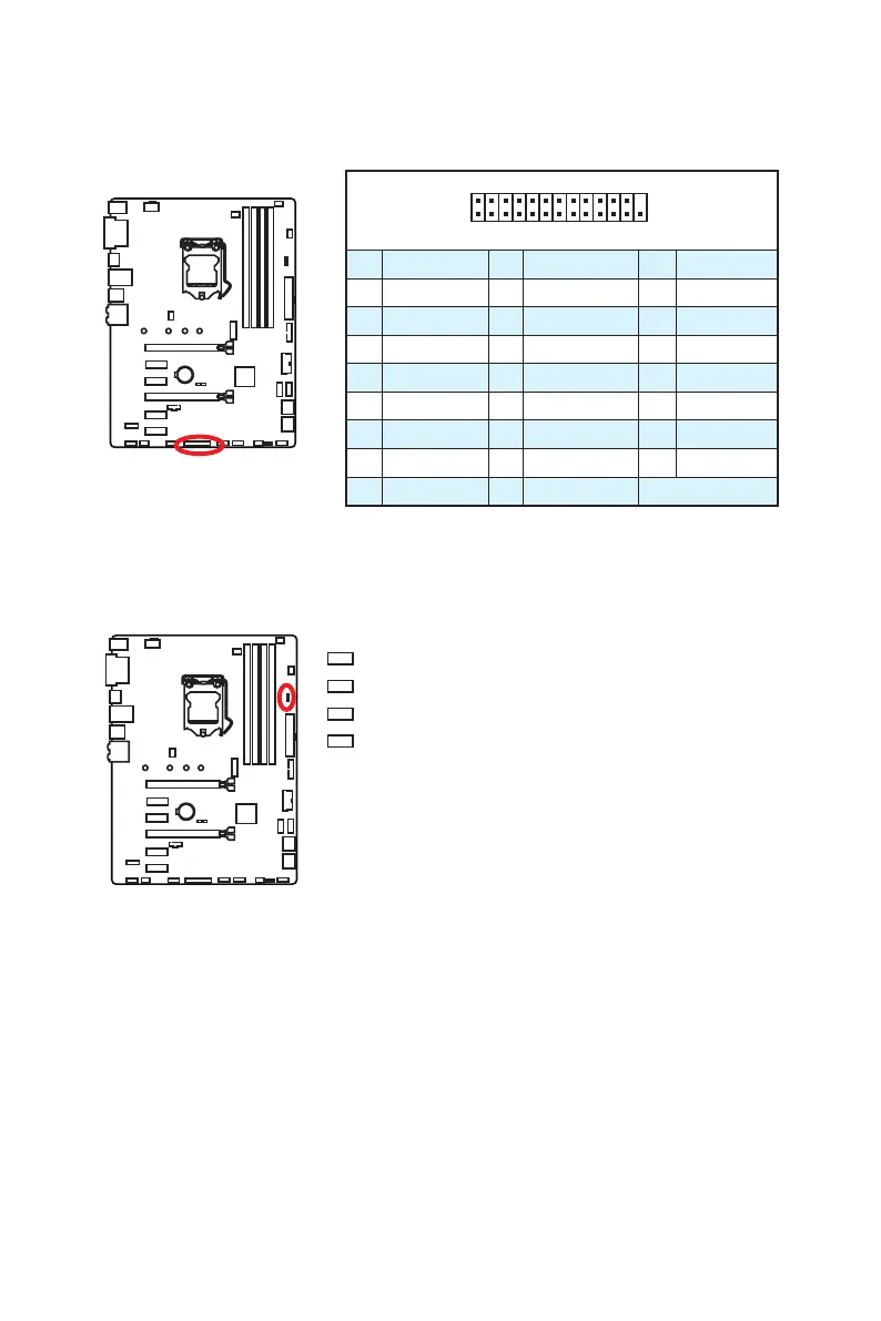
EZ Debug LED
These LEDs indicate the status of key components during booting process. When an
error is occurred, the corresponding LED stays lit until the problem is solved.
CPU - indicates CPU is not detected or fail.
DRAM - indicates DRAM is not detected or fail.
VGA - indicates GPU is not detected or fail.
BOOT - indicates the booting device is not detected
or fail.
 Loading...