Do you have a question about the MSI MS-6309 and is the answer not in the manual?
Details the mainboard's components and capabilities, including CPU, chipset, memory, and slots.
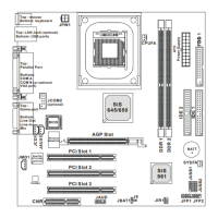
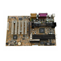
Diagram illustrating the layout of various connectors and components on the mainboard.
Information on CPU installation, socket type, and the need for a heatsink and fan.
Step-by-step guide for installing the CPU into the Socket 370.
Details connection procedures for CPU and system fans, including pin assignments and speed sensor usage.
Instructions for clearing CMOS settings using the JBAT1 jumper and battery.
Details the mainboard's memory support, including DIMM sockets and total capacity.
Step-by-step guide for physically installing a DIMM memory module into the socket.
Guidelines for installing SDRAM DIMMs, including compatibility and population order.
Diagram and description of the JFP1 connector for front panel switches and LEDs.
Details the primary and secondary IDE connectors for hard drives and CD-ROMs.
Information regarding the ATX 20-pin power connector and its functions.
Pin definition and function of the ATX 20-pin power connector for the mainboard.
Instructions for connecting a remote power switch and its functionality for power management.
Pin definition and function of the 9-pin male serial port connectors.
Pin definition and function of the 25-pin female parallel port connector.
Pin definition for the PS/2 mouse mini DIN connector.
Pin definition for the PS/2 keyboard mini DIN connector.
Pin definition and function of the USB connectors for peripheral devices.
Table mapping D-LED codes to descriptions, possible problems, and voice contexts.
Explains the JFSH1 jumper for locking/unlocking BIOS Flash operations.
Instructions on how to access the AMI BIOS setup utility by pressing the DEL key.
Guide to configuring date, time, and hard disk parameters in the Standard CMOS Setup.
Details on configuring boot devices, display modes, and other BIOS features.
Configuration options for SDRAM timing, DRAM frequency, and AGP settings.
Configuration options for system power management features like ACPI and LED status.
Configuration for Plug and Play operating system awareness and PCI device settings.
Configuration for onboard peripherals like IDE, Floppy, Serial, Parallel, Audio, Modem, and USB.
Monitors system hardware parameters like CPU temperature, fan speed, and voltages.
Sets up Supervisor and User passwords for system access and BIOS setup.
Step-by-step guide for installing VIA Chipset and AC97 Sound Drivers on Windows 98.
Detailed steps for installing VIA Atapi, AGP VxD, Chipset Functions Registry, and IRQ Routing drivers.
Instructions for installing the VIA AC97 PCI Sound Drivers and AC97 Audio Drivers.
Steps for installing VIA AC97 PCI Audio Device and VIA MIDI External Port drivers.
| Brand | MSI |
|---|---|
| Model | MS-6309 |
| Category | Motherboard |
| Language | English |