EasyManua.ls Logo

MSI MS-6120 User Manual

MSI MS-6120
50 pages
To Next Page IconTo Next Page
Page #1 background imageLoading...
Page #1 background image
CHAPTER 1 INTRODUCTION
1-1
Chapter 1
INTRODUCTION
The ATX BX2 mainboard is a high-performance dual-processor personal
computer mainboard based on the Intel
®
Pentium
®
II processor. The Intel
®
Pentium
®
II processor supports MMX
TM
(Multimedia Extension) technology.
The mainboard uses the highly integrated Intel
®
82440BX chipset to support
the PCI/ISA and Green standards, and to provide the Host/AGP bridge. The
82371EB chipset integrates all system control functions such as ACPI
(Advanced Configuration and Power Interface). The ACPI provides more
Energy Saving Features for the OSPM(OS Direct Power Management)
function. The Intel
®
82371EB chipset also improves the IDE transfer rate by
supporting Ultra DMA/33 IDE that transfers data at the rate of 33MB/s.
The mainboard also supports the System Hardware Monitor Controller as an
optional function. This function includes: CPU /power supply/chassis fan
revolution detect, CPU/system voltage monitor, system temperature monitor,
and chassis intrusion detect(optional).
Question and Answer IconNeed help?

Do you have a question about the MSI MS-6120 and is the answer not in the manual?

MSI MS-6120 Specifications

General IconGeneral
BrandMSI
ModelMS-6120
CategoryMotherboard
LanguageEnglish

Summary

Chapter 1 Introduction

1.1 Mainboard Features

Details the key features of the ATX BX2 mainboard, including CPU, chipset, memory, and expansion slots.

1.2 Mainboard Layout

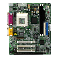
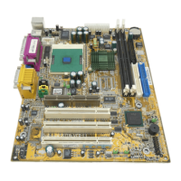
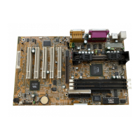
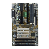
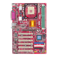
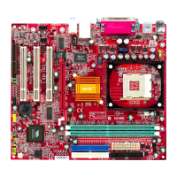
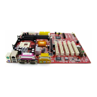
Illustrates the physical layout of components and connectors on the mainboard.

Chapter 2 Hardware Installation

2.1 Central Processing Unit: CPU

Provides detailed instructions for installing the Intel Pentium II processor, including OEM and boxed types.

2.2 Clear CMOS Jumper: JBAT1

Instructions for clearing CMOS settings using the JBAT1 jumper to reset system configuration.

2.3 Power On Mode Jumper: JIPWR

Configuration options for system boot-up modes: Boot-Up by Switch and Immediate Boot-Up.

2.4 Memory Installation

Guidance on installing SDRAM modules, memory bank configuration, and supported specifications.

2.5 Case Connector: JFP1

Connects case components like power switch, reset, LEDs, and speaker to the mainboard.

2.6 Floppy Disk Connector: FDC

Connector for floppy disk drives, supporting various disk formats.

2.7 Hard Disk Connectors: IDE1 & IDE2

Connectors for IDE devices, supporting master/slave configurations for drives and CD-ROMs.

2.8 Power Supply

Details the ATX 20-pin power connector, pin definitions, and power management features.

2.9 IrDA Infrared Module Connector: IR1

Connector for optional infrared modules for wireless data transmission.

2.10 Serial Port Connectors: COM A & COM B

Connectors for serial ports, enabling high-speed communication for peripherals.

2.11 Parallel Port Connector: LPT

Connector for parallel printers, supporting Enhanced and Extended Parallel Port capabilities.

2.12 Mouse Connector: JKBMS1

Connector for attaching a PS/2 mouse.

2.13 Keyboard Connector: JKBMS1

Connector for attaching a PS/2 keyboard.

2.14 USB Connector: USB

Connectors for Universal Serial Bus devices, providing versatile peripheral connectivity.

2.15 Sleep Switch Connector: JGS1

Connector for a power saving sleep switch.

2.16 Sleep LED Connector: JGL1

Connector for the sleep mode indicator LED.

2.17 Modem Wake Up Connector: JMDM1

Connector for modem add-on cards that support the modem wake-up function.

2.18 Wake-Up on LAN Connector: JWOL1

Connector for LAN add-on cards supporting the Wake-Up on LAN feature.

2.19 SB_Link™ Card Sound Connector: JSOUND

Connector for PCI sound cards, facilitating distributed DMA for sound processing.

2.20 CPU's Temperature Sensor: JSOR1/JSOR2

Sensors located near the heatsink to monitor CPU temperature.

2.21 Two Color Power LED: JWLED1

Connector for a two-color LED indicating normal and suspend system modes.

2.22 System Manager Jumper: JSM1

Jumper used to select the SMI# source for system management.

2.23 SCSI Connectors

Provides three on-board SCSI connectors for high-speed data transfer.

2.24 SCSI Enable/Disable Jumper: JDSCSI

Jumper to enable or disable the on-board SCSI controller chip.

Chapter 3 AMI® BIOS User's Guide

Enter BIOS Setup

Step-by-step instructions for accessing and navigating the BIOS setup utility for system configuration.

Related product manuals