2-15
Hardware Setup
JF_P1
1
8
Reset
HDD_LED
PWR_LED
PS-ON
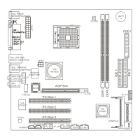
Front Panel Connector: JF_P1
The mainboard provides one front panel connector for electrical con-
nection to the front panel switches and LEDs.
Fan Power Connector: CFAN1
The CFAN1 (processor fan) supports system cooling fan with +12V. It
supports three-pin head connector. When connecting the wire to the connector,
always take note that the red wire is the positive and should be connected to
the +12V, the black wire is Ground and should be connected to GND.
Joystick/Game Connector: J3 (Optional)
You can connect a joystick or game pad to this connector.
CFAN1
Sensor
+12V
GND
MSI Reminds You...
Always consult the vendors for proper CPU cooling fan.
Pin Description Pin Description
1 FVCC5 (power) 2 Key pin
3 RXD 4 GP4
5 GP5 6 GP6
7 GP7 8 GP2
9 GP1 10 GP0
11 GP3 12 TXD
J3 Pin Definition
J3
1
11
2
12